# Overview

Welcome to the FSS Documentation Hub, our gateway to all documentation for our aircraft addons for Microsoft Flight Simulator. If you have additional question please [contact us](https://www.flightsim-studio.com/contact/) anytime.

<details>

<summary>E-Jets E17X/E19X (Early Access)</summary>

### Purchase

[Aerosoft](https://www.aerosoft.com/de/shop/microsoft-flight-simulator/msfs-flugzeuge/3979/flightsim-studio-e-jets-170/175)

[Contrail](https://contrail.shop/products/e-jets-175-msfs)

[Simmarket](https://secure.simmarket.com/aerosoft-flightsim-studio-e-jets-175-msfs.phtml)

[Flightsim.com](https://store.flightsim.com/FlightSim-Studio--E-Jets-170175_p_4907.html)

### Documentation

[Online Manual](https://docs.flightsim-studio.com/e-jet-series/)

</details>

<details>

<summary>Boeing 727 Series</summary>

### Purchase

727-200 Passenger: [Aerosoft](https://www.aerosoft.com/en/shop/flight/microsoft-flight-simulator/msfs-2020/msfs-flugzeuge/4548/flightsim-studio-b727-passenger) | [Contrail](https://contrail.shop/products/flightsim-studio-727-200-passenger-msfs?srsltid=AfmBOoo73MKZh5qwwYz_GFkCPpkrwliDlQLJOdnEgirtT55UzqOG5tW5) | [Simmarket](https://secure.simmarket.com/aerosoft-flightsim-studio-b727-passenger-msfs20-\(de_20001\).phtml)

727-200 Freighter: [Aerosoft](https://www.aerosoft.com/de/shop/flight/microsoft-flight-simulator/msfs-flugzeuge/4352/flightsim-studio-b727-freighter) | [Contrail](https://contrail.shop/products/fss-727-200-freighter-msfs) | [Simmarket](https://secure.simmarket.com/aerosoft-flightsim-studio-b727-freighter-msfs-\(de_19337\).phtml)

727-200 Super27 Expansion: [Aerosoft](https://www.aerosoft.com/en/shop/flight/microsoft-flight-simulator/msfs-2020/msfs-aircraft/4652/flightsim-studio-super-27-expansion-pack) | [Contrail](https://contrail.shop/products/flightsim-studio-super-27-expansion-msfs-2020-2024?srsltid=AfmBOopxKdpjQ5AyH0jv8Q3VXGG1AGyxfhHiksypR79rEtsiPWl-YLVX) | [Simmarket](https://secure.simmarket.com/aerosoft-flightsim-studio-super-27-expansion-pack-msfs2024-\(de_20525\).phtml)

727-100 Series (All In One): [Aerosoft](https://www.aerosoft.com/de/shop/flight/microsoft-flight-simulator/msfs-2020/msfs-flugzeuge/4724/flightsim-studio-b727-100-series) | [Contrail](https://contrail.shop/products/flightsim-studio-727-100-msfs-2020-2024)

### Documentation

[Online Documentation](https://docs.flightsim-studio.com/boeing-727/)

</details>

<details>

<summary>Tecnam P2012 Traveller</summary>

### Purchase

[Aerosoft](https://www.aerosoft.com/en/shop/flight/microsoft-flight-simulator/msfs-aircraft/4193/flightsim-studio-tecnam-p2012-traveller?number=AS16194)

[Contrail](https://contrail.shop/collections/msfs-aircraft/products/tecnam-p2012-traveller-msfs)

### Documentation

[Online Manual](https://docs.flightsim-studio.com/tecnam-p2012/)

</details>

<details>

<summary>Tecnam P2006T MKII</summary>

### Purchase

[Aerosoft](https://www.aerosoft.com/de/shop/microsoft-flight-simulator/msfs-flugzeuge/4019/flightsim-studio-tecnam-p2006t-mkii)

[Contrail](https://contrail.shop/collections/frontpage/products/tecnam-p2006t-mkii-msfs)

[Simmarket](https://secure.simmarket.com/aerosoft-flightsim-studio-tecnam-p2006t-mkii-msfs-\(de_17656\).phtml)

[Flightsim.com](https://store.flightsim.com/FlightSim-Studio--Tecnam-P2006T-MKII_p_4939.html)

### Documentation

[Online Manual](https://docs.flightsim-studio.com/tecnam-p2006t/)

</details>

<details>

<summary>Tecnam P2006T Analog</summary>

### Purchase

[Aerosoft](https://www.aerosoft.com/en/shop/flight/microsoft-flight-simulator/msfs-aircraft/4224/flightsim-studio-tecnam-p2006t-analog)

### Documentation

[Online Manual](https://docs.flightsim-studio.com/tecnam-p2006t-analog/)

</details>

<details>

<summary>SeaRey Elite</summary>

### Purchase

Aerosoft ([Light ](https://www.aerosoft.com/de/shop/microsoft-flight-simulator/msfs-flugzeuge/3916/aerosoft-aircraft-searey-elite-light)/ [Advanced](https://www.aerosoft.com/de/shop/microsoft-flight-simulator/msfs-flugzeuge/3915/aerosoft-aircraft-searey-elite-advanced))

Flightsim.to ([Light ](https://flightsim.to/product/aerosoft-aircraft-searey-elite-light)/ [Advanced](https://flightsim.to/product/aerosoft-aircraft-searey-elite-advanced))

Contrail ([Light ](https://contrail.shop/products/searey-elite-light-msfs)/ [Advanced](https://contrail.shop/products/searey-elite-advanced-msfs?_pos=1&_sid=96117a605&_ss=r))

Simmarket ([Light ](https://secure.simmarket.com/aerosoft-aerosoft-aircraft-searey-elite-light-msfs-\(de_17115\).phtml)/ [Advanced](https://secure.simmarket.com/aerosoft-aerosoft-aircraft-searey-elite-advanced-msfs-\(de_17116\).phtml))

### Documentation

[Online Manual](https://docs.flightsim-studio.com/searey-elite/)

</details>


# Welcome

The following documents are a comprehensive description of the feauters in the E-Jet Series product by FlightSim Studio AG for Microsoft Flight Simulator.

{% hint style="danger" %}
**Disclaimer**

Information in this documentation are intended for use solely with Microsoft Flight Simulator. The use for real world aviation is strictly prohibited.
{% endhint %}

{% hint style="info" %} <mark style="color:red;">**RED FONT**</mark> indicates features, that have not been implemented into the product (yet).
{% endhint %}

***

### Installation via Aerosoft One <a href="#installation-via-aerosoft-one" id="installation-via-aerosoft-one"></a>

For a detailed installation instruction please refer to the [Aerosoft One User Guide](https://docs.flightsim-studio.com/e-jet-series/introduction/cdnone.aerosoft.com/client/user-guide/en)

***

### Installation via Contrail App <a href="#installation-via-microsoft-marketplace" id="installation-via-microsoft-marketplace"></a>

No matter if you bought the E-Jets via the Contrail shop or any other shop you can use [Contrail - the multi store app](https://getcontrail.com/) to install and it.

The required serial number can be found in Aerosoft One or in the corresponding shop product page.

[How To Guide](https://contrail.shop/pages/activation/activate-fss-e-jets-170-175)

***

### Installation via Microsoft Marketplace <a href="#installation-via-microsoft-marketplace" id="installation-via-microsoft-marketplace"></a>

Unfortunately this addon is not available in the Microsoft Marketplace yet. We already delivered the package to Microsoft however it usually takes weeks to months for them to release it. We will keep you posted!

***

### Support <a href="#support" id="support"></a>

We feel strongly about support. Buying one of our products gives you the right to ask questions. We provide support in English only.

**Discord:** Join our [**server**](https://discord.com/invite/KE5sHcN6eR) to discuss and report issues directly with the team.

**E-Mail:** Please use our [**contact form**](https://www.flightsim-studio.com/contact/).

***

### Copyrights <a href="#copyrights" id="copyrights"></a>

The manual, documentation, video images, software, and all the related materials are copyrighted and cannot be copied, photocopied, translated, or reduced to any electronic medium or machine legible form, neither completely nor in part, without the previous written consent of AEROSOFT or FLIGHTSIM STUDIO AG.&#x20;

THE SOFTWARE IS FURNISHED «AS IS» AND IT DOES NOT COME FURNISHED WITH ANY GUARANTEE IMPLICIT OR EXPRESS. THE AUTHOR DECLINES EVERY RESPONSIBILITY FOR CONTINGENT MALFUNCTIONS, DECELERATION, AND ANY DRAWBACK THAT SHOULD ARISE, USING THIS SOFTWARE.&#x20;

Copyright © 2024 AEROSOFT / FlightSim Studio AG. All rights reserved. All trademarks and brand names are trademarks or registered trademarks of the respective owners.

Copyright Roboto Font by Google. Licensed under the Apache License, Version 2.0.

Copyrights are serious stuff. If you find any pirated copies of this software, please notify us at <support@flightsim-studio.com>. We will make sure reports of copyrights violation are rewarded.&#x20;

Aerosoft GmbH | Lindberghring 12 | D-33142 Büren, Germany

FlightSim Studio AG | Gartenstrasse 95 | 4052 Basel, Switzerland


# First Steps

### Familiarization <a href="#familiarization" id="familiarization"></a>

1. Set up a custom controls profile (see below).
2. Calibrate your throttle (see below).
3. Read the Procedure Guide.
4. Read the EFB pages (loading, settings, charts).
5. In case of any issue check out the FAQs first.

### Controls Assignments <a href="#controls-assignments" id="controls-assignments"></a>

The aircraft uses a very complex automatic logic which interfers with the use of key bindings. This can lead to malfunctions and significantly impair the flight. Therefore, we recommend that you create a separate controller profile for the E-Jets and delete the following key bindings:

* TOGGLE MASTER BATTERY AND ALTERNATOR
* TOGGLE MASTER ALTERNATOR

### Throttle Calibration <a href="#throttle-calibration" id="throttle-calibration"></a>

**The throttle calibration page can be accessed via EFB → Settings (gear, upper right) → Calibration tab**

![](https://cdn.document360.io/417c2d4d-fdb8-4d4d-b11d-011fe445d776/Images/Documentation/Throttle_Calibration_Legend.jpg)

***

**Axis Assignment**

Currently you can't bind your throttle axis to the "Throttle general" key.

* Please bind your axes to THROTTLE 1 AXIS and THROTTLE 2 AXIS.
* If you only have one throttle lever, bind them to THROTTLE AXIS.

![](https://cdn.document360.io/417c2d4d-fdb8-4d4d-b11d-011fe445d776/Images/Documentation/image-1674160023091.png)

***

**Deadzones**

For each detent position you can assign a minimum and maximum deadzone limit.

* The colors reflect the detent position (White = Idle, Green = TO/GA, Orange = MAX)
* The deadzone thresholds can be changed by dragging them up and down.

![](https://cdn.document360.io/417c2d4d-fdb8-4d4d-b11d-011fe445d776/Images/Documentation/image-1674158377926.png)

***

**LINK AXIS**

Click to synchronize left and right axis. The applied method is indicated with a gree dot. To disable axis linking just click on the LINK AXIS button again.

![](https://cdn.document360.io/417c2d4d-fdb8-4d4d-b11d-011fe445d776/Images/Documentation/image-1674157955819.png)

* Left > Right: Sync left axis to right axis
* Left < Right: Sync right axis to left axis
* Average: Sync based on the average of both axis
* Minimum Level: Sync the axis with the lowest value to higher axis
* Maximum Level: Sync the axis with the highest value to the lower axis

{% hint style="info" %}
**Single Throttle Lever**

If your hardware throttle only has one lever, you don't have to link the axes because they are already linked by the axis binding in the MSFS control options.
{% endhint %}

***

**REV ON AXIS**

Activating this puts the reverser to your current axis. 0% equals maximum reverse. Disabling this option sets 0% back to idle thrust.

![](https://cdn.document360.io/417c2d4d-fdb8-4d4d-b11d-011fe445d776/Images/Documentation/image-1674158603284.png)

***

**LINK SETTINGS**

Synchronizes the last deadzone changes to the other side. Use this after configuring one axis to set up the other one with the same deadzones by one click.

![](https://cdn.document360.io/417c2d4d-fdb8-4d4d-b11d-011fe445d776/Images/Documentation/image-1674158093721.png)


# FAQs

### Can I improve my framerate? <a href="#can-i-improve-my-framerate" id="can-i-improve-my-framerate"></a>

Currently, all screens in the cockpit are rendered individually. This means that the more displays are active, the more has to be calculated. Performance can be increased if screens are switched off (e.g. on the copilot side) by dimming the brightness knobs next to the Primary Flight Display.

You can also lower per-display caps on EFB → Settings → **Aircraft** → **Display Refresh Rate** (PFD, MFD, MCDU, EICAS, IESS, EFB). The maximum follows the MSFS **Glass Cockpit Refresh Rate**.

***

### How can I add weight & fuel? <a href="#how-can-i-add-weight-amp-fuel" id="how-can-i-add-weight-amp-fuel"></a>

Navigate to **Departure** on the [EFB](/e-jet-series/special-features/electronic-flight-bag/flight-management). Import SimBrief or enter weights, then **Begin Loading** (Real-time, Instant, or GSX).

Please don't use the in-game weight menu — it conflicts with the custom weight-and-balance logic.

***

### Are there known incompatibilities? <a href="#known-incompatibilities" id="known-incompatibilities"></a>

**Other 3rd party addons**

Unfortunately, some 3rd party addons are not programmed optimally, so that they overwrite certain standard functions or displays in the MSFS and change their behavior, which in turn affects our aircraft. The following errors can occur:

* The DRM popup window does not appear
* The aircraft doesn't appear in the selection menu
* The whole addon crashes

To prevent this, we strongly recommend using an addon linker (e.g. the free [MSFS Addons Linker](https://de.flightsim.to/file/1572/msfs-addons-linker) Tool) to activate only one aircraft addon per session and prevent mutual misbehavior.

The following 3rd party addons have already been identified as problematic by our community, although no guarantee can be given for correctness and completeness.

* RLTS Ultimate Traffic
* [Bishop Rock Lighthouse (Helipad)](https://de.flightsim.to/file/15955/bishop-rock-lighthouse-helipad)
* [BGAA - Aasiaat Greenland](https://de.flightsim.to/file/4467/bgaa-aasiaat-greenland)
* [BGBW Narsarsuaq Greenland](https://de.flightsim.to/file/734/bgbw-narsarsuaq-greenland)
* [BGCO - Nerlerit Greenland](https://de.flightsim.to/file/3614/bgco-nerlerit)
* [BGJN - Ilulissat](https://flightsim.to/file/4833/bgjn-ilulissat)
* [BGKK - Kulusuk Greenland](https://de.flightsim.to/file/3662/bgkk-kulusuk)
* [BGMQ - MANIITSOQ AIRPORT, GREENLAND](https://secure.simmarket.com/pearl-simulations-2-bgmq-maniitsoq-airport-greenland-msfs-\(de_15562\).phtml)
* [BGMQ - Maniitsoq Greenland](https://de.flightsim.to/file/4384/bgmq-maniitsoq-greenland)
* [BGSS - Sisimiut Greenland](https://de.flightsim.to/file/4433/bgss-sisimiut-greenland)
* [BGUQ Qaarsut Greenland](https://de.flightsim.to/file/3856/bguq-qaarsut-airport)
* [BIKF Keflavik Airport](https://orbxdirect.com/product/mkstudios-bikf-msfs)
* [Iqaluit Airport (CYFB) Enhancement for Asobo's CYFB](https://de.flightsim.to/file/57466/iqaluit-airport-cyfb-enhancement-for-asobo-s-cyfb)
* [TL Creation Greenland Enhancement Pack](https://de.flightsim.to/file/45487/tl-creation-greenland-enhancement-pack)
* [CowanSim Bell 222](https://cowansim.com/product/222b-for-msfs/)
* [CowanSim MD 500](https://secure.simmarket.com/cowan-simulation-cowansim-500e-msfs-\(de_17540\).phtml)
* [Carenado PC-12](https://www.carenado.com/sitecarenado/product/pc12-msfs/)
* [Cockspur C510 Mustang](https://cockspur.eu/product/cockspur-c510-mustang)
* [Shift+Z Stats](https://de.flightsim.to/file/16358/shift-z-stats)
* [SimportTeam - Canakkale Airport LTBH](https://flightsim.to/file/9300/simportteam-canakkale-airport-ltbh-turkey)
* [MSFS Map Enhancement](https://de.flightsim.to/file/19345/msfs-2020-google-map-replacement)

If you want to read up the technical problem behind this story, please check out [this article](https://devsupport.flightsimulator.com/t/vfs-we-need-to-find-a-way-to-stop-this-madness/7273).

***

### Autopilot doesn't intercept the ILS properly <a href="#autopilot-doesn-t-intercept-the-ils-properly" id="autopilot-doesn-t-intercept-the-ils-properly"></a>

The custom autopilot and flight director are implemented (including ILS LOC/GS, VNAV, and go-around). Follow the intercept procedure in the [Procedure Guide](/e-jet-series/normal-procedures/procedure-guide#approach).

***

### What's the difference between "TO Pitch" and "Trim"?

"TO Pitch" refers to the initial pitch attitude for takeoff, displayed as a magenta bar on the flight director. It's not the same as trim. Setting an takeoff trim incorrectly can make rotation difficult. To find the correct trim value, use the Electronic Flight Bag (EFB) to load flight details and check the manifest tab for the "TRM" value. Confirm this value on the EICAS display. Before takeoff, ensure proper configuration by performing a TO Config check, which verifies flap settings, parking brake, spoilers, and trim within the green band on the EICAS.

***

### FMS is refusing Waypoint/SID/STAR <a href="#fms-is-refusing-waypoint-sid-star" id="fms-is-refusing-waypoint-sid-star"></a>

The aircraft uses a custom FMS (Honeywell-style MCDU), not the default MSFS flight plan. See the [MCDU Guide](/e-jet-series/mcdu-guide/basics) for RTE, SID/STAR, and waypoint entry. Navdata must match the cycle in the FMS ([Navdata Updater](broken://pages/RB3qdkkr2I37RuCdYo27)). Invalid idents still show **NOT IN DATABASE**.

***

### Import Flightplans (i.e. from Simbrief) <a href="#import-flightplans-i-e-from-simbrief" id="import-flightplans-i-e-from-simbrief"></a>

Please follow our Procedure Guide.

***

### PFD/MFD lags <a href="#pfd-mfd-lags" id="pfd-mfd-lags"></a>

Please apply the recommended settings described here.

***

### How to exit keyboard entry in FMS <a href="#how-to-exit-keyboard-entry-in-fms" id="how-to-exit-keyboard-entry-in-fms"></a>

Enable **MCDU Keyboard Entry** on EFB → Settings → **Aircraft**, then **click** the MCDU to capture the keyboard (green scratchpad border). **Tab** releases it. Moving the cursor away is not required.

Shortcuts: [MCDU Basics](/e-jet-series/mcdu-guide/basics#keyboard-entry).

***

### Throttle doesn't work <a href="#throttle-doesn-t-work" id="throttle-doesn-t-work"></a>

Please read the throttle calibration section in First Steps.

***

### Reverse without axis <a href="#reverse-without-axis" id="reverse-without-axis"></a>

If you have no axis to assign to throttle reverse mode you have to map your button to TOGGLE THROTTLE REVERSE THRUST. If you then press the button your throttle axis will switch to reverse. If you advance it, reverse thrust will increase. Put it back to idle and then press your button again to leave reverser mode.

Make sure that REV on AXIS is not activated in the EFB throttle configuration.

***

### Where can I download free liveries? <a href="#where-can-i-download-free-liveries" id="where-can-i-download-free-liveries"></a>

There are several liveries at [flightsim.to](https://flightsim.to/c/liveries/flightsim-studio-e-jets-175/) available for free.

***

### Are there custom simbrief profiles available?

Yes, please get them here:

***

### Is there a GSX configuration available? <a href="#is-there-a-gsx-configuration-available" id="is-there-a-gsx-configuration-available"></a>

Yes, head over here:

***

### Is there a paintkit available? <a href="#is-there-a-paintkit-available" id="is-there-a-paintkit-available"></a>

For the E170 and E190/195 we got an official paintkit including layered tifs and a blender 3D file for a quick preview.

[DOWNLOAD E170 PaintKit](https://www.dropbox.com/s/i72swfd7wmoyo0e/PaintKit%20E170%20\(version%200.9.10%2B\).zip?dl=0)

[DOWNLOAD E19X PaintKit](https://www.dropbox.com/scl/fi/kj1bviwgur6lugpjlyg09/PaintKit-E19X.zip?rlkey=8wwt4dandg5gpdszjkcm2wfam\&dl=0)

{% hint style="info" %}
The E175 still uses some kind of legacy object structure which will be changed some day and therefore no official paintkit is available yet.
{% endhint %}


# How To Update

Before updating or reinstalling the E-Jets, we strongly recommend that you delete all E-Jets files - including those that remain after a standard uninstallation. This refers to the so-called work folder, which is stored under your computer user directory. This folder acts as a cache for the aircraft. With too many updates, this cache can easily get messed up and lead to strange problems after an update.

To make this process as easy as possible for you, we have created a script that takes care of this for you. Download, exctract wherever you like and simply run it. It will list all found work folders, which can then be deleted with your confirmation.

{% file src="/files/7LY88HJd9nrL9MKMQvhF" %}

{% hint style="success" %}
Don't worry, saved settings of the EFB, such as Simbrief username or throttle configuration, etc., will remain intact. You won't need to reconfigure all your settings.
{% endhint %}

## Update Flow

1. Uninstall our aircraft entirely.
2. Run the batch script or follow manual deletion.
3. Start MSFS and load a flight in any other aircraft.
4. Close MSFS.
5. Install our aircraft again.

<details>

<summary>Manual Deletion</summary>

If you prefer not to run the script and would rather delete the folders manually, you can find them here:

`%USERPROFILE%\AppData\Local\Packages\Microsoft.FlightSimulator_8wekyb3d8bbwe\LocalState\packages`

or

`%USERPROFILE%\AppData\Roaming\Microsoft Flight Simulator\Packages`

Delete all folders starting with `fss-aircraft-e`.

</details>


# Things to know

We’re currently working on a version with a completely custom-built Flight Management System. This is a complex project, and we have a team of around 200 testers who review our progress almost every week.

#### Installation

If you’d like a behind-the-scenes look, you can switch to the **Experimental branch**.

**Aerosoft One**

1. Go to the product library and select the E-Jets.
2. Uninstall the aircraft if you already have it installed.
3. The experimental installation is in light grey at the bottom.

<figure><img src="https://2148350057-files.gitbook.io/~/files/v0/b/gitbook-x-prod.appspot.com/o/spaces%2F4zuBab090JlaOR4WgDz8%2Fuploads%2FX40BLYujaBnY70cXGNt6%2Fimage.png?alt=media&#x26;token=6b3a8c79-2491-4f10-9002-3842248d1850" alt=""><figcaption></figcaption></figure>

**Contrail**

1. Go to the respective product page in the Contrail App.
2. Uninstall the aircraft if you already have it installed.
3. Then you will see two installation options: Stable and Experimental.

<figure><img src="https://2148350057-files.gitbook.io/~/files/v0/b/gitbook-x-prod.appspot.com/o/spaces%2F4zuBab090JlaOR4WgDz8%2Fuploads%2Fq00YOK7jinTVx58EWptV%2Fimage.png?alt=media&#x26;token=f300c74f-691a-49e0-afb1-69d3b9ff4cdd" alt=""><figcaption></figcaption></figure>

#### What is Experimental?

Experimental is a snapshot of our internal test build. It’s only updated occasionally when we reach major milestones. Smaller changes are tested exclusively by our beta team.

#### What’s included in Experimental?

The new custom FMS is already integrated. This brings improved LNAV and VNAV (FLCH / PATH / ASEL / ALT / GP), go-around, back course, CAT II / autoland FMA status, overspeed protection, and PFD PLI. Windshear guidance is not included.

#### What should I expect?

This version is **buggy**. Many things may not work as you’re used to, and crashes can happen.

#### Where can I report bugs?

Nowhere. We have a dedicated internal test team that reports bugs based on our own requirements. No action is needed from you.

#### Where can I get support?

There is no support for this version. It’s strictly experimental, and support will only be available once version 1.0 is released.

#### How do I switch back to the Stable version?

Simply uninstall the E-Jets and select the **Stable branch** during reinstallation.


# Checklist

{% hint style="danger" %}
**Disclaimer**

The following content is based on a real checklist of the aircraft type, but is adapted to the flight simulator version and therefore not to be used for real aviation.
{% endhint %}

### SAFETY AND POWER UP <a href="#safety-and-power-up" id="safety-and-power-up"></a>

| <p><strong>FLIGHT DECK</strong><br></p>         | **CHECKED**                     |
| ----------------------------------------------- | ------------------------------- |
| <p><strong>EMERGENCY EQUIPMENT</strong><br></p> | **CHECKED**                     |
| **MAINTENANCE STATUS**                          | **CHECKED**                     |
| **GPU**                                         | **OUT**                         |
| **APU GEN**                                     | **IN**                          |
| **BATTERIES 1 & 2**                             | **OFF**                         |
| **FUEL PUMPS**                                  | **AUTO**                        |
| **EMERGENCY LIGHT**                             | **OFF**                         |
| **WINDSHIELD WIPERS**                           | **OFF**                         |
| **HYDRAULIC SYS 1, 2, & 3B ELEC PUMPS**         | **AUTO**                        |
| **HYDRAULIC SYS 3 ELEC PUMP A**                 | **OFF**                         |
| **LANDING GEAR LEVER**                          | **DN**                          |
| **POWERPLANT START / STOP 1 & 2**               | **STOP**                        |
| **SPEED BRAKE LEVER**                           | **CLOSE**                       |
| **THRUST LEVERS**                               | **IDLE**                        |
| **BATTERIES 1 & 2**                             | **ON / AUTO**                   |
| **SLAT/FLAP LEVER**                             | **AGREES WITH SURFACE POSITON** |
| **FIRE EXTINGUISHER PANEL**                     | **CHECKED**                     |
| **ELECTRICAL POWER / AIR CONDITIONING**         | **ESTABLISH**                   |

### BEFORE START <a href="#before-start" id="before-start"></a>

| **PREFLIGHT CHECKS**   | **COMPLETE**          |
| ---------------------- | --------------------- |
| **FUEL QTY**           | **CHECKED**           |
| **MCDU**               | **SET**               |
| **CREW OXYGEN**        | **CHECKED**           |
| **ALTIMETER**          | **SET and X-CHECKED** |
| **FLIGHT INSTRUMENTS** | **SET**               |
| **PASSENGER SIGNS**    | **ON**                |
| **TAKEOFF BRIEFING**   | **COMPLETE**          |

\---------------------------------

| **SEATBELT / SHOULDER HARNESS**                                                                                                                                                                    | **CHECKED**                                                                                                                                                                                         |
| -------------------------------------------------------------------------------------------------------------------------------------------------------------------------------------------------- | --------------------------------------------------------------------------------------------------------------------------------------------------------------------------------------------------- |
| **TAKEOFF PERFORMANCE**                                                                                                                                                                            | **SET**                                                                                                                                                                                             |
| **AUTOBRAKE**                                                                                                                                                                                      | **RTO**                                                                                                                                                                                             |
| **TRIM**                                                                                                                                                                                           | **SET, CENTERED**                                                                                                                                                                                   |
| **DOORS / WINDOWS**                                                                                                                                                                                | **CLOSED**                                                                                                                                                                                          |
| **BEACON**                                                                                                                                                                                         | **ON**                                                                                                                                                                                              |
| **TRANSPONDER**                                                                                                                                                                                    | **ON**                                                                                                                                                                                              |
| **PARKING BRAKE**                                                                                                                                                                                  | **OFF**                                                                                                                                                                                             |
| <p><strong>ENGINE</strong><br><strong>INGITION A / B</strong><br><strong>FUEL FLOW</strong><br><strong>OIL PRESS</strong><br><strong>IGNITION A / B OUT</strong><br><strong>TIMER</strong><br></p> | <p><strong>START 1 / 2</strong><br><strong>at 7% N2</strong><br><strong>at 20% N2</strong><br><strong>within 10 SECONDS</strong><br><strong>at 50% N2</strong><br><strong>2 MIN WARMUP</strong></p> |

### AFTER START  <a href="#after-start" id="after-start"></a>

| **FLAPS**                       | **SET**         |
| ------------------------------- | --------------- |
| **APU**                         | **AS REQUIRED** |
| **HYDRAULIC SYS 3 ELEC PUMP A** | **ON**          |
| **FLIGHT CONTROLS**             | **CHECKED**     |
| **TAXI LIGHT NOSE / SIDE**      | **ON**          |

### BEFORE TAKEOFF <a href="#before-takeoff" id="before-takeoff"></a>

| **CABIN**                                | **SECURED**  |
| ---------------------------------------- | ------------ |
| **TAKEOFF DATA**                         | **REVIEWED** |
| **EICAS**                                | **CHECKED**  |
| **BRAKE TEMP**                           | **CHECKED**  |
| **TAKEOFF CONFIG**                       | **CHECKED**  |
| **LIGHTS STROBE / LANDING / INSPECTION** | **ON**       |

### AFTER TAKEOFF <a href="#after-takeoff" id="after-takeoff"></a>

| **LANDING GEAR** | **UP**  |
| ---------------- | ------- |
| **APU**          | **OFF** |
| **SLAT/FLAPS**   | **UP**  |

### DESCENT <a href="#descent" id="descent"></a>

| **LIGHTS AND SEAT BELT SIGNS**   | **SET**      |
| -------------------------------- | ------------ |
| **ALTIMETER**                    | **SET**      |
| **LANDING DATA**                 | **REVIEWED** |
| **AUTOBRAKE**                    | **SET**      |
| **SEAT BELT / SHOULDER HARNESS** | **CHECKED**  |
| **APPROACH BRIEFING**            | **COMPLETE** |

### BEFORE LANDING <a href="#before-landing" id="before-landing"></a>

| **FLIGHT ATTENDANTS** | **NOTIFIED**     |
| --------------------- | ---------------- |
| **LANDING GEAR**      | **DOWN 3 GREEN** |
| **FLAPS**             | **SET**          |
| **LANDING LIGHT**     | **ON**           |

### AFTER LANDING <a href="#after-landing" id="after-landing"></a>

| **LIGHTS** | **AS REQUIRED**    |
| ---------- | ------------------ |
| **FLAPS**  | **UP**             |
| **TRIM**   | **4 UP, CENTERED** |
| **APU**    | **START**          |

### SHUTDOWN <a href="#shutdown" id="shutdown"></a>

| **TRANSPONDER**       | **OFF** |
| --------------------- | ------- |
| **CHOCKS AND BRAKES** | **SET** |
| **ENGINES**           | **OFF** |
| **HYDRAULIC PUMP 3A** | **OFF** |


# Limitations

### WEIGHT <a href="#weight" id="weight"></a>

* **Max Ramp:** 38.950 kg | 85.870 lb
* **Max T/O:** 38.790 kg | 85.517 lb
* **Max Lnd:** 34.000 kg | 74.957 lb
* **Max ZFW:** 31.700 kg | 69.886 lb
* **Max FWD Cargo:** 1.500 kg | 3.306 lb
* **Max AFT Cargo:** 1.150 kg | 2.535 lb

### STRUCTURAL <a href="#structural" id="structural"></a>

* **Wing Span:** 12,16 m | 39 ft 11 in
* **Aircraft Length:** 31,67 m | 103 ft 11 in
* **Tail Height:** 9,86 m | 32 ft 4 in

### ALT & TEMPS <a href="#alt-amp-temps" id="alt-amp-temps"></a>

* **Max Ops Altitude:** 41.000 ft
* **Max Single Pack Ops:** 31.000 ft
* **Max Flaps/Slats Ops:** 20.000 ft
* **Max T/O & Lnd:** 10.000 ft
* **Max T/O & Lnd Temp:** ISA + 35°C
* **Min T/O & Lnd Temp:** -40°C
* **RWY Slope:** 2/- 2%

### FLAPS <a href="#flaps" id="flaps"></a>

* **VFE 1**: 230 kt
* **VFE 2**: 215 kt
* **VFE 3**: 200 kt
* **VFE 4**: 180 kt
* **VFE 5**: 180 kt
* **VFE FULL**: 165 kt
* **Min Spoiler Speed:** 180 kts
* **Max Flaps/Slats Ops:** 20.000 ft
* **CAT II Ops:** Flaps 5
* **Landing Flaps Full:** Go Around Flaps 4
* **Landing Flaps 5**: Go Around Flaps 2

### ENGINES <a href="#engines" id="engines"></a>

* **ITT Max Temp:** 815°C
* **Min Oil Press:** 25 psi
* **ATTCS OFF T/O:** Not authorized

### FUEL <a href="#fuel" id="fuel"></a>

* **Max Fuel Capacity:** 9496 kg | 20.935 lb
* **Max Imbalance:** 360 kg | 794 lb
* **Min Fuel Tank Temp:** -37°C
* **Min Fuel:** 1020 kg | 2250 lb / 45 min
* **Emergency Fuel:** 680 kg | 1500 lb / 30 min
* **X Feed T/O & Lnd:** Off
* **Single Tank Indications:** Amber (600 kg | 1320 lb) / Red (300 kg | 660 lb)
* **Dual Tank Indications:** Amber (1200 kg | 2640 lb) / Red (600 kg | 1320 lb)

### PRESSURIZATION <a href="#pressurization" id="pressurization"></a>

* **Max Differential Press:** 8.4 psi
* **Max Differential Overpress:** 8.8 psi
* **Max Differential Neg. Press:** -0.5 psi
* **Max Differential Press T/O & Lnd:** 0.2 psi

### ANTI ICE <a href="#anti-ice" id="anti-ice"></a>

**On Ground**

**ENG:** OAT is 5°C  - 10°C  and

* visible moisture possible up to 1.700 ft AFE
* snow, ice standing water, or slush may be injested or freeze on engines, nacelles, or sensors

**ALL:** OAT is <5°C  and

* visible moisture possible up to 1.700 ft AFE
* snow, ice standing water, or slush may be injested or freeze on engines, nacelles, or sensors

**In Flight**

When either one or both ice detectors are failed, the crew must set the mode selector to ON when icing conditions exist or are anticipated below 10°C TAT with visible moisture.

### SPEEDS & X WIND <a href="#speeds-amp-x-wind" id="speeds-amp-x-wind"></a>

**V SPEEDS**

* **VX:** Green Dot
* **VY:** Green Dot + 50 kt
* **VMO (SL - 8.000):** 300 kt
* **VMO (10.000 - Mach Transition):** 320 kt
* **MMO:** 0.82m
* **VA:** 240 kt
* **VLO:** 250 kt
* **VTIRE:** 195 kt
* **VRAT MAX:** VMO / MMO
* **VRAT MIN:** 130 kt
* **VB (<10.000 ft):** 250 kt
* **VB (>10.000 ft):** 270 kt / 0.76m
* **VWIPERS:** 250 kt
* **VWINDOW:** 160 kt
* **VTAXI (Dry Straight):** 30 kt
* **VTAXI (Dry Turn):** 10 kt
* **VTAXI (Wet Straight):** 10 kt
* **VTAXI (Wet Turn):** 5 kt

#### XWIND

**Takeoff**

* **Dry:** 38 kt
* **Wet:** 31 kt
* **Compact Snow:** 20 kt
* **Dry/Wet Snow, Slush, Stndg Water:** 18 kt
* **Ice:** 12 kt
* **Wet Ice:** 12 kt

**Tailwind**

* Max Tailwind: 15 kt

**Holding**

* **Min Hold (< 6.000 ft):** 200 kt
* **Min Hold (6.000 - 14.000 ft):** 230 kt
* **Min Hold (> 14.000 ft):** 265 kt

### BATTERY <a href="#battery" id="battery"></a>

* **Min Voltage:** 22.5v
* **Min Recharge Voltage:** 22.4v - 21.1v
* **Min Maintenance Voltage:** 21v

### STARTER <a href="#starter" id="starter"></a>

**Ground Start**

* **1 & 2:** 90 sec ON / 10 sec OFF
* **3 - 5:** 90 sec On / 5 min OFF

**In Flight Start**

* **1 & 2:** 120 sec ON / 10 sec OFF
* **3 - 5:** 120 sec On / 5 min OFF

**Dry Motoring**

* **1 & 2:** 90 sec ON / 5 min OFF
* **3 - 5:** 30 sec On / 5 min OFF

### APU <a href="#apu" id="apu"></a>

Wait 30 sec after EICAS energization for APU Start

**Starter Duty Cicle**

* **1 & 2:** 60 sec OFF
* **3:** 5 min OFF

**Start Op Limits**

* **Min Temp:** -54°C
* **Max Temp:** ISA + 35°C
* **Altitude:** 30.000 ft

**Continuous Op Limits**

* **Min Temp:** -54°C
* **Max Temp:** ISA + 35°C
* **Altitude:** 33.000 ft
* **Electrical Generator Use:** 33.000 ft
* **Engine Start:** 21.000 ft
* **Bleed Use:** 15.000 ft

### HYDRAULICS & BRAKES <a href="#hydraulics-amp-brakes" id="hydraulics-amp-brakes"></a>

* **Min Resevoir Temp for ENG Start:** -18°C
* **Brake Temp for T/O:** Green
* **Thrust Reversers:**
  * No Go Around after deployment
  * Do not move levers into forward thrust until REV icon shown in amber or green
  * No thrust reversers for power back ops
  * No thrust reversers during taxi ops

### MISC. <a href="#misc" id="misc"></a>

**Autopilot**

* **Min Engagement Height:** 400 ft
* **Min Use Height:** 50 ft
* **Min Use HEight (Non Prec. App):** MDA

**NAV Equipment**

* TAS, TAT, & SAT only valid above 60 kt
* Mag Compass invalid while VHF1 transmitting
* Baro mins must be used for all CAT 1 Approaches

**EGPWS**

* NAV not predicated on use of Terr Aware Sys
* Manually inhibit EGPWS when Indg at airport not in database


# Approach Types

### Side by side comparison of approach types

| Approach Type                       | Sub Category    | Needle Color | Minimums                         | Arm Approach |
| ----------------------------------- | --------------- | ------------ | -------------------------------- | ------------ |
| ILS with vertical guidance          | CAT 1 ILS       | Green        | DA (BARO)                        | APP          |
| ILS with vertical guidance          | CAT 2 ILS       | Green        | RA                               | APP          |
| RNAV and VOR with vertical guidance | RNP             | Magenta      | DA                               | APP          |
| RNAV and VOR with vertical guidance | LPV & LNAV/VNAV | Magenta      | DA                               | APP          |
| RNAV and VOR                        | LNAV            | Magenta      | MDA + 50 ft                      | APP          |
| RNAV and VOR                        | VOR             | Magenta      | MDA + 50 ft                      | APP          |
| Localizer without vertical guidance | Localizer       | Magenta      | MDA rounded up to nearest 100 ft | NAV          |

**RNAV Notes**

* Use RNAV and VOR profile for RNAV-RNP, RNAV-GPS, RNAV/FMS Visual, and VOR approaches.
* VOR approaches are treated like an RNAV approach (flown in magenta needles, armed with APP). Have the VOR frequency and course set up in preview (cyan needles) as backup during the approach.
* RNAV/GPS with vertical guidance captures **GP** (glide path). FMA armed status shows **L/VNAV** or **LPV** depending on the procedure.
* After GP or GS is captured, set ALTSEL to the missed-approach altitude. ALTSEL is ignored during GS and GP.

**ILS / CAT II Notes**

* CAT I: minimums = BARO. Disconnect AP by 200 ft AGL.
* CAT II: both PFDs on RA minimums (same value), both NAV receivers on the ILS, dual valid NAV. FMA shows **APPR 2**.
* Back-course: CRS = **front course**. Use NAV or APP. GS is inhibited. See FGCS Lateral Modes.

**Localizer Notes**

* Localizer approaches are flown similar to an RNAV approach.
* Localizer approach minimums: take the published minimum and round it up to the nearest hundred feet.


# Procedure Guide

> For the complete documentation index, see [llms.txt](https://docs.flightsim-studio.com/llms.txt). Markdown versions of documentation pages are available by appending `.md` to page URLs; this page is available as [Markdown](https://docs.flightsim-studio.com/e-jet-series/normal-procedures/procedure-guide.md).

## Procedure Guide

{% hint style="info" %}
**Please note**

Different procedures are used depending on the operator. The following explanations are therefore only exemplary.
{% endhint %}

#### Flight Planning <a href="#flight-planning" id="flight-planning"></a>

For a step-by-step MCDU screenshot walkthrough (route, SID/STAR, PERF INIT, takeoff speeds), see Preflight Setup (Quick Guide).

* Performance planning via [Simbrief](https://www.simbrief.com/home/) is recommended to use the default E170 or E175 profile. The weights have been adapted to these profiles.
* Direct route import into the MCDU is possible via 2 ways:

**World Map menu**

1. Export your flightplan as msfs flightplan file (.FLT) (i.e. Simbrief, SimtoolkitPro, etc.).
2. In MSFS World Map menu import your flightplan file (LOAD/SAVE->LOAD FROM THIS PC).
3. The route will automatically be added to the E-Jets MCDU upon flight initialization.

**SimBrief MCDU import**

Store your SimBrief username in **NAV → DATALINK → ADDRESS**, then use **SEND** on **RTE** (route) and **SEND REQST** on **PERF INIT** (performance). Match origin, destination, and **FLIGHT ID** to your OFP. SID, STAR, and runway are not imported — select them on the MCDU.

Full procedure: SimBrief Import.

We also have a video guide available:

#### Power Up <a href="#power-up" id="power-up"></a>

![](https://cdn.document360.io/417c2d4d-fdb8-4d4d-b11d-011fe445d776/Images/Documentation/Powerup\(2\).jpg)

1. **BATTERIES ............................................... ON**
2. **GPU AVAIL ................................................. IN**
3. **APU .................................... ON, then START**
4. **NAV LIGHT ............................................... ON**
5. **LOGO LIGHT ......................... AS REQUIRED**
6. **EMER LIGHT ..................................... ARMED**

#### **Pushback** <a href="#pushback" id="pushback"></a>

* **Default MSFS Option:** works fine
* [**Toolbar Pushback**](https://de.flightsim.to/file/15033/toolbar-pushback)**:** works fine
* [**GSX Pro**](https://www.fsdreamteam.com/products_gsxpro.html)**:** works but requires custom profile.

#### Startup <a href="#startup" id="startup"></a>

* To avoid power interruptions it is recommended to wait 30 s after the %N2 stabilizes before shutting the APU down or GPU disconnection, or to use the Electrical Synoptic Page to follow the power transfer.

![](https://cdn.document360.io/417c2d4d-fdb8-4d4d-b11d-011fe445d776/Images/Documentation/Startup.jpg)

1. **FSTN BELTS SIGN .................................... ON**
2. **BEACON .................................................... ON**
3. **ENGINE 1 / 2 ...................................... START**

#### **After Startup** <a href="#after-startup" id="after-startup"></a>

<figure><img src="https://cdn.document360.io/417c2d4d-fdb8-4d4d-b11d-011fe445d776/Images/Documentation/AfterStartup.jpg" alt=""><figcaption></figcaption></figure>

1. **APU ........................................ AS REQUIRED**
2. **ELEC PUMP A............................................ ON**
3. **TAXI LIGHTS ............................................. ON**
4. **FLAPS ....................................................... SET**

#### Taxi <a href="#taxi" id="taxi"></a>

* The E-Jets tend to start rolling on idle thrust when releasing parking brake. Increased weight reduces that effect.
* In order to allow thermal stabilization of the engines, operate them at or near IDLE for at least 2 minutes before selecting high trust settings. Taxi time at or near IDLE can be included in the warm up period.
* Single Engine Taxi is allowed.
* **VTAXI (Dry Straight):** 30 kt
* **VTAXI (Dry Turn):** 10 kt
* **VTAXI (Wet Straight):** 10 kt
* **VTAXI (Wet Turn):** 5 kt

{% hint style="info" %}
During initial roll it might be neccessary to counteract engine thrust pitch up moment by some nose down input on elevator to increase nose wheel steering effectiveness.
{% endhint %}

#### Before Takeoff <a href="#before-takeoff" id="before-takeoff"></a>

* T/O config button must be pressed until you hear an aural feedback to check aircraft configuration.
* TOGA Button on Throttle lever must be pressed before takeoff by latest to set the autoflight system into takeoff mode. Most operators do that prior startup.

![](https://cdn.document360.io/417c2d4d-fdb8-4d4d-b11d-011fe445d776/Images/Documentation/BeforeTakeoff.jpg)

1. **APU ........................................ AS REQUIRED**
2. **STROBE LIGHT ........................................ ON**
3. **INSP LIGHT .............................................. ON**
4. **LANDING LIGHT ..................................... ON**
5. **T/O CONFIG ................................. CHECKED**

**Stab Trim**

| **ALL WEIGHTS** |                         |        |        |        |        |        |        |        |        |        |     |
| --------------- | ----------------------- | ------ | ------ | ------ | ------ | ------ | ------ | ------ | ------ | ------ | --- |
| **FLAP**        | **CG POSITION (% MAC)** |        |        |        |        |        |        |        |        |        |     |
| **7**           | **9**                   | **11** | **13** | **15** | **17** | **19** | **21** | **23** | **25** | **27** |     |
| **1**           | 6.0                     | 6.0    | 5.5    | 5.0    | 5.0    | 4.5    | 4.0    | 3.5    | 3.0    | 3.0    | 2.5 |
| UP              | UP                      | UP     | UP     | UP     | UP     | UP     | UP     | UP     | UP     | UP     |     |
| **2**           | 6.0                     | 6.0    | 5.5    | 5.0    | 4.5    | 4.0    | 3.5    | 3.5    | 3.0    | 2.5    | 2.0 |
| UP              | UP                      | UP     | UP     | UP     | UP     | UP     | UP     | UP     | UP     | UP     |     |
| **4**           | 6.0                     | 5.5    | 5.0    | 4.5    | 4.0    | 3.5    | 3.0    | 2.5    | 2.0    | 1.5    | 1.0 |
| UP              | UP                      | UP     | UP     | UP     | UP     | UP     | UP     | UP     | UP     | UP     |     |

#### Takeoff <a href="#takeoff" id="takeoff"></a>

* Ensure takeoff mode has been armed (FMAs on PFD).
* Arm Autothrottle by pressing the corresponding button on glareshield panel.
* Adjust thrust to 40% N1. When engines stabilize at 40% N1, advance thrust levers to TO/GA detent. Autothrottle will take over at 50% N1.
* Minimum airspeed at positive rate: V2 + 10

#### Climb <a href="#climb" id="climb"></a>

* Arm **VNAV** on the ground (or after takeoff). Magenta **FLCH** captures above the VNAV CAP AFE (default 800 ft).
* Set ALTSEL to the cleared altitude. VNAV will not climb through ALTSEL.
* If VNAV is not used, fly green **FLCH**. Target speed: 250 - 270 kt IAS.

#### Enroute <a href="#enroute" id="enroute"></a>

* Autothrottle will disconnect if throttles are being used by user input. Exception: Airspeed is less than 60 kts.

#### Descent <a href="#descent" id="descent"></a>

* Set ALTSEL to the cleared altitude **before** TOD. One minute before TOD, **VTA** is displayed.
* With VNAV and LNAV active, magenta **PTH** captures the descent path. Speed from FMS or MAN.
* If ALTSEL is not wound down, the airplane stays in VALT through TOD.
* For a non-precision approach, press **APP** to arm **GP**, then set missed-approach altitude in ALTSEL after GP is captured — same flow as ILS GS.
* If VNAV is not used, fly FPA and plan to the according values. Add additional distance for speed reduction if necessary.

*Required distance = (Current Altitude - Target altitude) / Slope equivalent*

* **3 degree slope:** 320ft per nm
  * Example: *(30.000ft - 3.000ft) / 320ft/nm = 84nm*
* **3.5 degree slope:** 375ft per nm
  * Example: *(30.000ft - 3.000ft) / 375ft/nm = 72nm*
* **4.0 degree slope:** 425ft per nm
  * Example: *(30.000ft - 3.000ft) / 425ft/nm = 64nm*

#### Approach <a href="#approach" id="approach"></a>

**ILS Auto Tune**

Since v0.9.9 we implemented the Auto Tune feature. It will automatically set up the ILS frequency and course if

* ILS approach is selected in MCDU and
* Aircraft is within 150nm from destination

If you change the approach type in MCDU while autotune is active:

* ILS approach but different runway: frequency and course will get updated automatically
* other than ILS approach: autotune gets deactivated

If ILS frequency or course gets overwritten by user input autotune gets disconnected.

You can toggle it on/off in any MCDU NAV page:

* Click on MCDU radio button
* Click on LSK next to any standby frequency to enter NAV page
* Toggle Auto Tune mode via LSK 5R

**ILS Auto Preview**

Since v0.9.9 we implemented the Auto Preview feature. When in FMS source mode, PREV will automatically be activated and set to NAV1/2 (depending on AP source) with ILS frequency and course if

* ILS approach is selected in MCDU and
* Aircraft is within 150nm from destination

When in FMS source mode and auto tune is active it will automatically change nav source to V/L (NAV1 or 2) when

* LOC is armed and
* Localizer needle starts to move

{% hint style="info" %}
You can arm LOC and GS by pressing APP when FMS source is still active and LOC1/2 is visible in preview. Once the auto tuning mode switches the nav source to V/L it will start to capture the LOC (and GS later on).
{% endhint %}

{% hint style="warning" %}
When in FMS source mode and APP is pressed without PREV active on NAV1/2 nothing will happen.
{% endhint %}

**ILS Manual Intercept**

* Approach the localizer with a 30 degree intercept in **HDG**.
* Once the localizer needle on the PFD starts moving, press **APP** on the glareshield (or use Auto Tune / Preview as above).

**RNAV / LPV / LNAV-VNAV**

* FMS NAV source, approach in the flight plan, **LNAV** and **VNAV** active.
* Press **APP** to arm **GP** (within 30 NM of destination, non-localizer approach, LOC preview off).
* Do not use green APP/LOC for these approaches.

**CAT II**

* RA minimums on both PFDs, both NAVs on the ILS, AP and YD on.
* Confirm white **APPR 2** before GS capture.

**Go-around**

* Press **TOGA**. Vertical **GA** and lateral **TRACK** engage. Autothrottle commands go-around thrust.

#### Landing <a href="#landing" id="landing"></a>

* As in the real aircraft the Speed Retard Mode will activate 30ft above ground. However the speed reduction is quite slow resulting in a long flare. Best practice for landing:
  * At MA/DA disconnect AT
  * At 50 ft raise the nose slightly
  * At 30 ft reduce throttle to idle and raise the nose to make the end of the runway not move up or down (usually 6-7 degrees nose up pitch)
  * When nose gear is on ground, apply reverse thrust
  * At 80 kts set reverse idle
  * At 60 kts reverse is stowed


# Preflight Setup (Quick Guide)

Step-by-step MCDU preflight from **RADIO** through a complete route, departure and arrival procedures, performance initialization, and takeoff speeds.

Example route: **EGLC/27** N0317F210 ODUK1A ODUKU M84 CLN P44 RATLO M197 REDFA REDF1A **EHAM/18R** (SimBrief / datalink import).

{% hint style="info" %}
Complete **NAV IDENT** once before using **RTE**, **FPL**, or **PERF** (verify the AIRAC cycle; update via [Navdata Updater](https://docs.flightsim-studio.com/e-jet-series/special-features/electronic-flight-bag/navdata-updater) if needed). Store your SimBrief username before route import. Keep the **EFB manifest** open for ZFW, fuel, **TO CG**, and V-speeds.
{% endhint %}

{% hint style="danger" %}
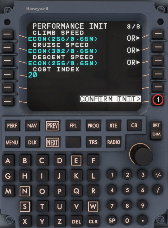
On **PERF INIT 3/3**, you must press **CONFIRM INIT>** before the FMS calculates the vertical profile (TOC/TOD) and VNAV data.
{% endhint %}

## Step 1

{% columns %}
{% column width="64%" %}

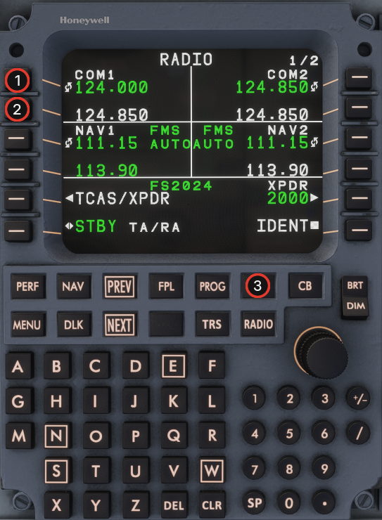
1. Enter the airport ground/delivery frequency (or the first frequency you will contact) on **RADIO**.
2. Enter the follow-up frequency in standby.
3. Press **RTE**.
   {% endcolumn %}

{% column width="36%" %} <img src="https://2148350057-files.gitbook.io/~/files/v0/b/gitbook-x-prod.appspot.com/o/spaces%2F4zuBab090JlaOR4WgDz8%2Fuploads%2FOLxXLw6ZSmcTEsMbQecp%2Fmcdu-preflight-step-01.png?alt=media" alt="MCDU Step 1" width="100%">
{% endcolumn %}
{% endcolumns %}

## Step 2

{% columns %}
{% column width="64%" %}

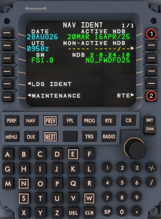
1. Open **NAV IDENT** and verify the loaded navdata cycle against the current date.
2. If navdata is out of date, follow the [Navdata Updater](https://docs.flightsim-studio.com/e-jet-series/special-features/electronic-flight-bag/navdata-updater) process (**EFB → Settings → Navdata**, or the desktop fallback).
   {% endcolumn %}

{% column width="36%" %} <img src="https://2148350057-files.gitbook.io/~/files/v0/b/gitbook-x-prod.appspot.com/o/spaces%2F4zuBab090JlaOR4WgDz8%2Fuploads%2Ft56XvdYHomEx6Luf944L%2Fmcdu-preflight-step-02.png?alt=media" alt="MCDU Step 2" width="100%">
{% endcolumn %}
{% endcolumns %}

## Step 3

{% columns %}
{% column width="64%" %}

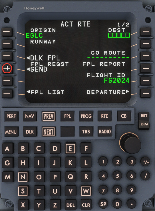
1. If your SimBrief username or userid is stored, import the latest route from **ACT RTE**.
2. Use **DLK FPL** (LSK 3L) or **SEND** (LSK 4L) after origin, destination, and **FLIGHT ID** match your OFP.
3. See SimBrief Import.
   {% endcolumn %}

{% column width="36%" %} <img src="https://2148350057-files.gitbook.io/~/files/v0/b/gitbook-x-prod.appspot.com/o/spaces%2F4zuBab090JlaOR4WgDz8%2Fuploads%2FrPYNPf20NJ2B0jEdM0nk%2Fmcdu-preflight-step-03.png?alt=media" alt="MCDU Step 3" width="100%">
{% endcolumn %}
{% endcolumns %}

## Step 4

{% columns %}
{% column width="64%" %}

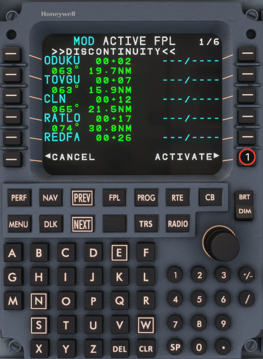
1. Verify the imported waypoints on the datalink flight-plan list.
2. **ACTIVATE** (or **APPLY ACTIVE**) to load the route into the active plan.
   {% endcolumn %}

{% column width="36%" %} <img src="https://2148350057-files.gitbook.io/~/files/v0/b/gitbook-x-prod.appspot.com/o/spaces%2F4zuBab090JlaOR4WgDz8%2Fuploads%2F3JYFVpXley0KNhad9uj1%2Fmcdu-preflight-step-04.png?alt=media" alt="MCDU Step 4" width="100%">
{% endcolumn %}
{% endcolumns %}

## Step 5

{% columns %}
{% column width="64%" %}

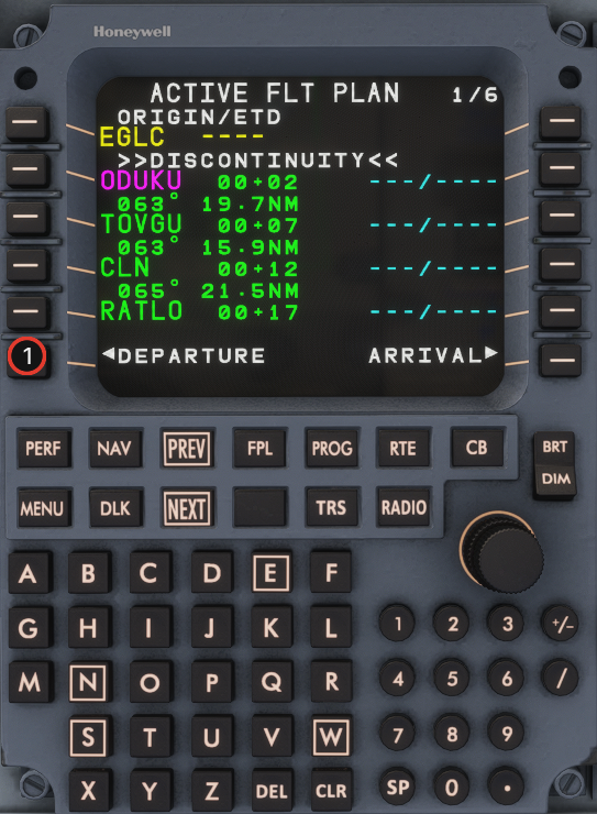
1. On **ACT RTE**, select **DEPARTURE>** (LSK 6R) to open departure procedures.
   {% endcolumn %}

{% column width="36%" %} <img src="https://2148350057-files.gitbook.io/~/files/v0/b/gitbook-x-prod.appspot.com/o/spaces%2F4zuBab090JlaOR4WgDz8%2Fuploads%2FwuaDwbRiDdAQxH6bxp1y%2Fmcdu-preflight-step-05.png?alt=media" alt="MCDU Step 5" width="100%">
{% endcolumn %}
{% endcolumns %}

## Step 6

{% columns %}
{% column width="64%" %}

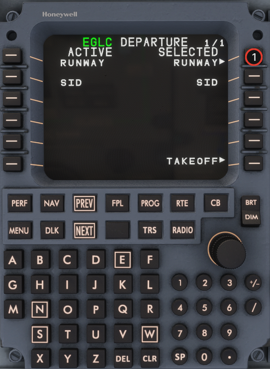
1. Open runway selection for the departure airport.
   {% endcolumn %}

{% column width="36%" %} <img src="https://2148350057-files.gitbook.io/~/files/v0/b/gitbook-x-prod.appspot.com/o/spaces%2F4zuBab090JlaOR4WgDz8%2Fuploads%2FyQEG2zkjVaNvamT0V4dG%2Fmcdu-preflight-step-06.png?alt=media" alt="MCDU Step 6" width="100%">
{% endcolumn %}
{% endcolumns %}

## Step 7

{% columns %}
{% column width="64%" %}

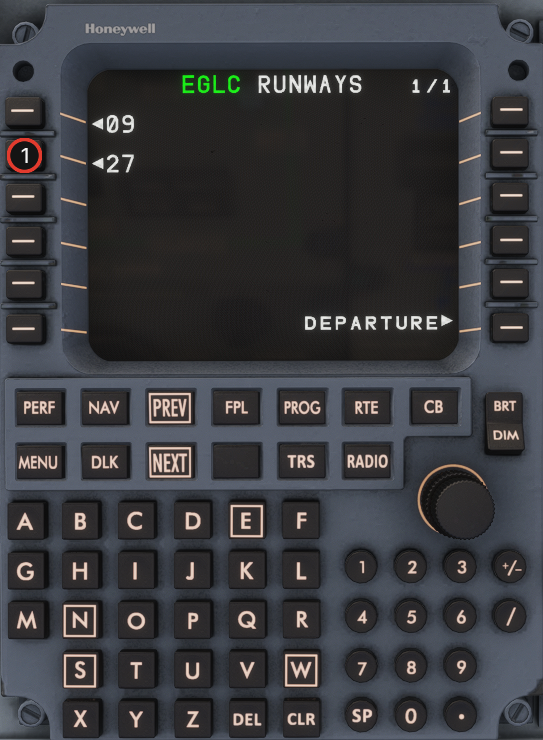
1. Select the planned departure runway.
   {% endcolumn %}

{% column width="36%" %} <img src="https://2148350057-files.gitbook.io/~/files/v0/b/gitbook-x-prod.appspot.com/o/spaces%2F4zuBab090JlaOR4WgDz8%2Fuploads%2F3mqdQENX9XqZZGSPqarp%2Fmcdu-preflight-step-07.png?alt=media" alt="MCDU Step 7" width="100%">
{% endcolumn %}
{% endcolumns %}

## Step 8

{% columns %}
{% column width="64%" %}

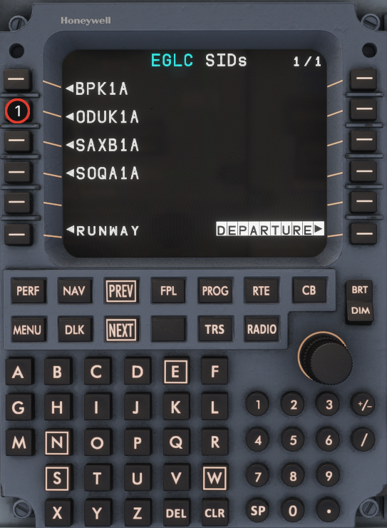
1. Select the planned SID.
   {% endcolumn %}

{% column width="36%" %} <img src="https://2148350057-files.gitbook.io/~/files/v0/b/gitbook-x-prod.appspot.com/o/spaces%2F4zuBab090JlaOR4WgDz8%2Fuploads%2FLwfH42oma55KWGx2t0ri%2Fmcdu-preflight-step-08.png?alt=media" alt="MCDU Step 8" width="100%">
{% endcolumn %}
{% endcolumns %}

## Step 9

{% columns %}
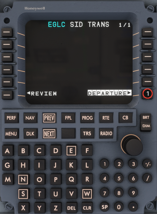
{% column width="64%" %}

1. Confirm the selected departure procedure.
   {% endcolumn %}

{% column width="36%" %} <img src="https://2148350057-files.gitbook.io/~/files/v0/b/gitbook-x-prod.appspot.com/o/spaces%2F4zuBab090JlaOR4WgDz8%2Fuploads%2F0wrgRtMFACvGZwswg1RO%2Fmcdu-preflight-step-09.png?alt=media" alt="MCDU Step 9" width="100%">
{% endcolumn %}
{% endcolumns %}

## Step 10

{% columns %}
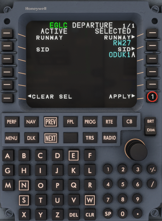
{% column width="64%" %}

1. **INSERT/APPLY** the departure procedure into the **MOD** flight plan.
   {% endcolumn %}

{% column width="36%" %} <img src="https://2148350057-files.gitbook.io/~/files/v0/b/gitbook-x-prod.appspot.com/o/spaces%2F4zuBab090JlaOR4WgDz8%2Fuploads%2F2xi3b4Y84hlLU5CiEixE%2Fmcdu-preflight-step-10.png?alt=media" alt="MCDU Step 10" width="100%">
{% endcolumn %}
{% endcolumns %}

## Step 11

{% columns %}
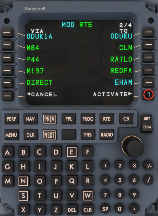
{% column width="64%" %}

1. Review the **MOD ACTIVE FPL**.
2. **ACTIVATE** (LSK 6R) to make the departure procedure active.
   {% endcolumn %}

{% column width="36%" %} <img src="https://2148350057-files.gitbook.io/~/files/v0/b/gitbook-x-prod.appspot.com/o/spaces%2F4zuBab090JlaOR4WgDz8%2Fuploads%2FFwTFyQ2M0gsBllF7HqRI%2Fmcdu-preflight-step-11.png?alt=media" alt="MCDU Step 11" width="100%">
{% endcolumn %}
{% endcolumns %}

## Step 12

{% columns %}
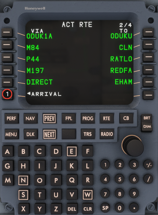
{% column width="64%" %}

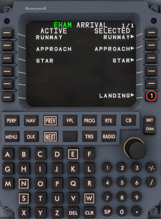
1. Return to **ACT RTE** and select **ARRIVAL>** (LSK 6R).
   {% endcolumn %}

{% column width="36%" %} <img src="https://2148350057-files.gitbook.io/~/files/v0/b/gitbook-x-prod.appspot.com/o/spaces%2F4zuBab090JlaOR4WgDz8%2Fuploads%2FfAsKUpDODVbFuMx21JKI%2Fmcdu-preflight-step-12.png?alt=media" alt="MCDU Step 12" width="100%">
{% endcolumn %}
{% endcolumns %}

## Step 13

{% columns %}
{% column width="64%" %}

1. Open runway selection for the arrival airport.
   {% endcolumn %}

{% column width="36%" %} <img src="https://2148350057-files.gitbook.io/~/files/v0/b/gitbook-x-prod.appspot.com/o/spaces%2F4zuBab090JlaOR4WgDz8%2Fuploads%2FkItVv98NS2PzVV1f2NJS%2Fmcdu-preflight-step-13.png?alt=media" alt="MCDU Step 13" width="100%">
{% endcolumn %}
{% endcolumns %}

## Step 14

{% columns %}
{% column width="64%" %}

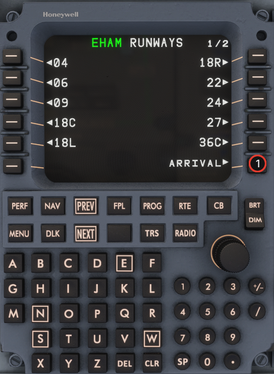
1. Select the planned arrival runway.
   {% endcolumn %}

{% column width="36%" %} <img src="https://2148350057-files.gitbook.io/~/files/v0/b/gitbook-x-prod.appspot.com/o/spaces%2F4zuBab090JlaOR4WgDz8%2Fuploads%2Fu8cVZJ0n2hugN5l8So8m%2Fmcdu-preflight-step-14.png?alt=media" alt="MCDU Step 14" width="100%">
{% endcolumn %}
{% endcolumns %}

## Step 15

{% columns %}
{% column width="64%" %}

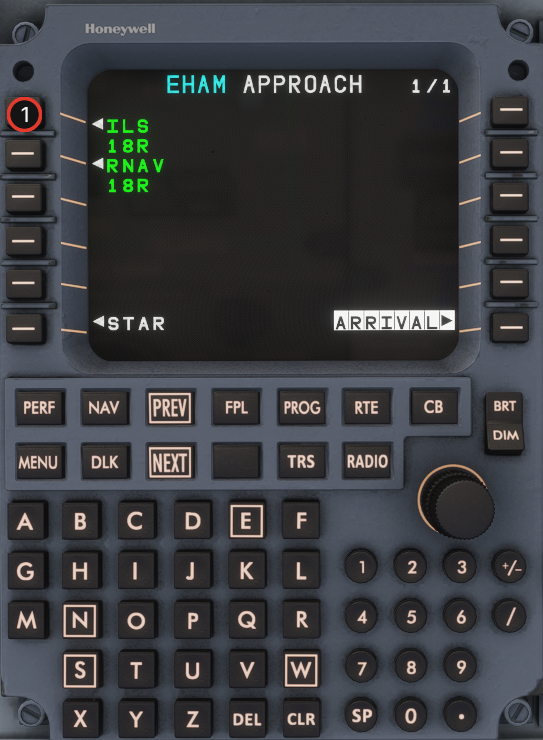
1. Select the planned approach procedure.
   {% endcolumn %}

{% column width="36%" %} <img src="https://2148350057-files.gitbook.io/~/files/v0/b/gitbook-x-prod.appspot.com/o/spaces%2F4zuBab090JlaOR4WgDz8%2Fuploads%2F2PsPgD1qMq6WltVMbLTr%2Fmcdu-preflight-step-15.png?alt=media" alt="MCDU Step 15" width="100%">
{% endcolumn %}
{% endcolumns %}

## Step 16

{% columns %}
{% column width="64%" %}

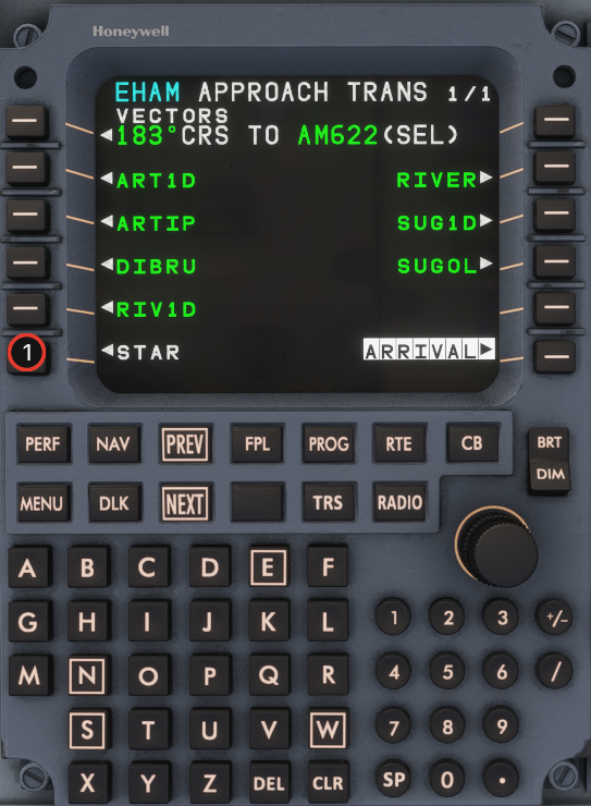
1. If you do not use an approach transition, skip directly to **STAR** selection.
   {% endcolumn %}

{% column width="36%" %} <img src="https://2148350057-files.gitbook.io/~/files/v0/b/gitbook-x-prod.appspot.com/o/spaces%2F4zuBab090JlaOR4WgDz8%2Fuploads%2FFIlYWIfY8b3gfe2cWtJ3%2Fmcdu-preflight-step-16.png?alt=media" alt="MCDU Step 16" width="100%">
{% endcolumn %}
{% endcolumns %}

## Step 18

{% columns %}
{% column width="64%" %}

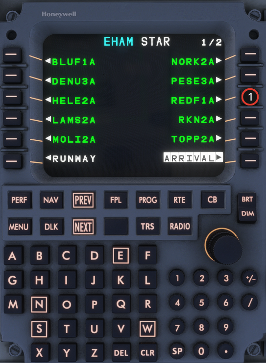
1. Select the planned STAR.
   {% endcolumn %}

{% column width="36%" %} <img src="https://2148350057-files.gitbook.io/~/files/v0/b/gitbook-x-prod.appspot.com/o/spaces%2F4zuBab090JlaOR4WgDz8%2Fuploads%2FhmMJYV0ZNNaxSLYHusxQ%2Fmcdu-preflight-step-18.png?alt=media" alt="MCDU Step 18" width="100%">
{% endcolumn %}
{% endcolumns %}

## Step 19

{% columns %}
{% column width="64%" %}

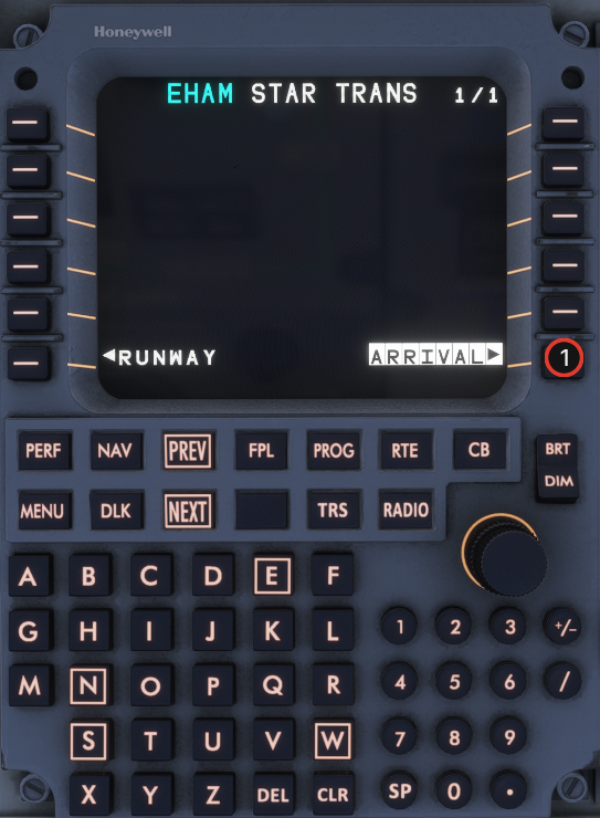
1. Confirm the selected arrival procedure.
   {% endcolumn %}

{% column width="36%" %} <img src="https://2148350057-files.gitbook.io/~/files/v0/b/gitbook-x-prod.appspot.com/o/spaces%2F4zuBab090JlaOR4WgDz8%2Fuploads%2FS1CSdkG02YgYwy5DVdlV%2Fmcdu-preflight-step-19.png?alt=media" alt="MCDU Step 19" width="100%">
{% endcolumn %}
{% endcolumns %}

## Step 20

{% columns %}
{% column width="64%" %}

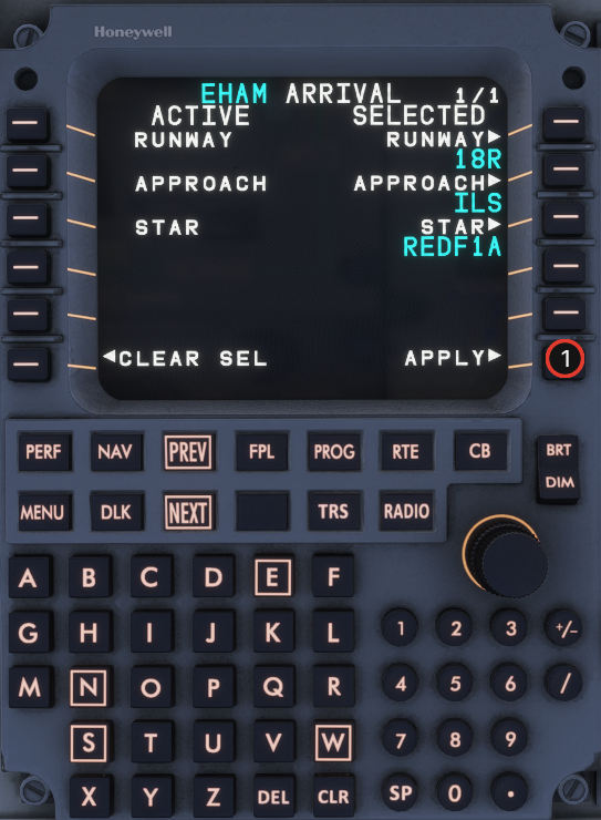
1. **INSERT/APPLY** the arrival procedure into the **MOD** flight plan.
   {% endcolumn %}

{% column width="36%" %} <img src="https://2148350057-files.gitbook.io/~/files/v0/b/gitbook-x-prod.appspot.com/o/spaces%2F4zuBab090JlaOR4WgDz8%2Fuploads%2FKyognuQkla3D1m0GOkqJ%2Fmcdu-preflight-step-20.png?alt=media" alt="MCDU Step 20" width="100%">
{% endcolumn %}
{% endcolumns %}

## Step 21

{% columns %}
{% column width="64%" %}

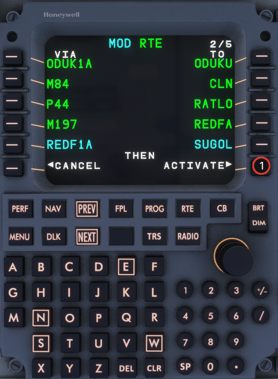
1. Review the **MOD ACTIVE FPL**.
2. **ACTIVATE** (LSK 6R).
   {% endcolumn %}

{% column width="36%" %} <img src="https://2148350057-files.gitbook.io/~/files/v0/b/gitbook-x-prod.appspot.com/o/spaces%2F4zuBab090JlaOR4WgDz8%2Fuploads%2F7Cg3F9pwKijdwBzw2jq3%2Fmcdu-preflight-step-21.png?alt=media" alt="MCDU Step 21" width="100%">
{% endcolumn %}
{% endcolumns %}

## Step 23

{% columns %}
{% column width="64%" %}

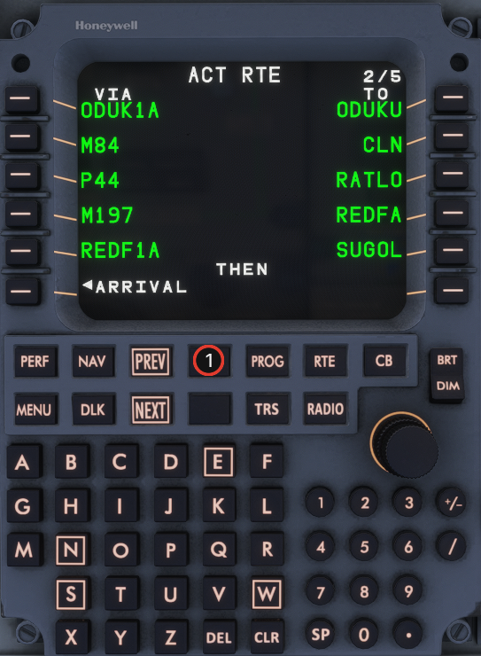
1. Press **FPL** and scan the active flight plan for discontinuities (`>>DISCONTINUITY<<`).
   {% endcolumn %}

{% column width="36%" %} <img src="https://2148350057-files.gitbook.io/~/files/v0/b/gitbook-x-prod.appspot.com/o/spaces%2F4zuBab090JlaOR4WgDz8%2Fuploads%2FDBTEYzXrJCjsvdyHCh7B%2Fmcdu-preflight-step-23.png?alt=media" alt="MCDU Step 23" width="100%">
{% endcolumn %}
{% endcolumns %}

## Step 24

{% columns %}
{% column width="64%" %}

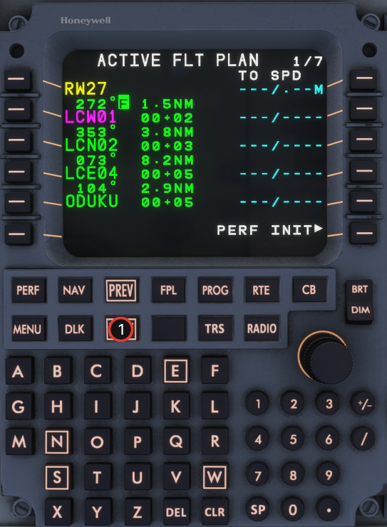
1. Use **NEXT** to walk through all flight-plan pages and check legs and constraints.
   {% endcolumn %}

{% column width="36%" %} <img src="https://2148350057-files.gitbook.io/~/files/v0/b/gitbook-x-prod.appspot.com/o/spaces%2F4zuBab090JlaOR4WgDz8%2Fuploads%2FW9lTLzvjbRwL27M6DRJ3%2Fmcdu-preflight-step-24.png?alt=media" alt="MCDU Step 24" width="100%">
{% endcolumn %}
{% endcolumns %}

## Step 26

{% columns %}
{% column width="64%" %}

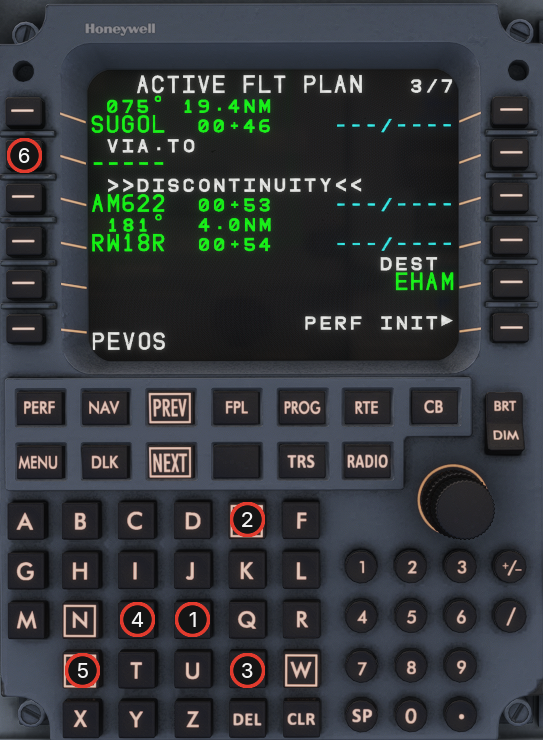
1. If a discontinuity remains (example on page 3/7), type the missing waypoint in the scratchpad (e.g. **PEVOS**).
2. Press the left LSK next to the discontinuity (dashed line) to insert the waypoint.
   {% endcolumn %}

{% column width="36%" %} <img src="https://2148350057-files.gitbook.io/~/files/v0/b/gitbook-x-prod.appspot.com/o/spaces%2F4zuBab090JlaOR4WgDz8%2Fuploads%2FCdDWQXKsoRmuc5dgEniQ%2Fmcdu-preflight-step-26.png?alt=media" alt="MCDU Step 26" width="100%">
{% endcolumn %}
{% endcolumns %}

## Step 28

{% columns %}
{% column width="64%" %}

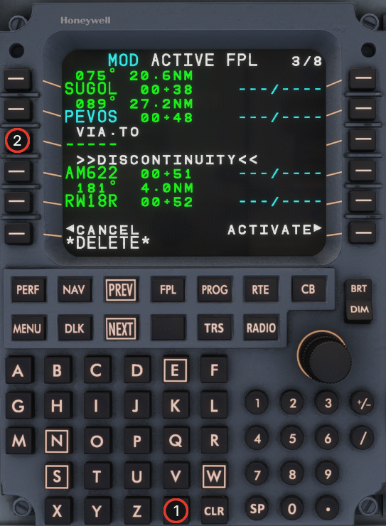
1. Press **DEL** to put `*DELETE*` in the scratchpad.
2. Delete the discontinuity dashes on the flight-plan page.
   {% endcolumn %}

{% column width="36%" %} <img src="https://2148350057-files.gitbook.io/~/files/v0/b/gitbook-x-prod.appspot.com/o/spaces%2F4zuBab090JlaOR4WgDz8%2Fuploads%2FXowObWgJKKwObS26AgC7%2Fmcdu-preflight-step-28.png?alt=media" alt="MCDU Step 28" width="100%">
{% endcolumn %}
{% endcolumns %}

## Step 29

{% columns %}
{% column width="64%" %}

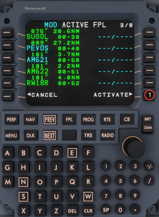
1. Review the **MOD** flight plan.
2. **ACTIVATE** (LSK 6R).
   {% endcolumn %}

{% column width="36%" %} <img src="https://2148350057-files.gitbook.io/~/files/v0/b/gitbook-x-prod.appspot.com/o/spaces%2F4zuBab090JlaOR4WgDz8%2Fuploads%2FStl7qWUvFU4yURKREFhx%2Fmcdu-preflight-step-29.png?alt=media" alt="MCDU Step 29" width="100%">
{% endcolumn %}
{% endcolumns %}

## Step 30

{% columns %}
{% column width="64%" %}

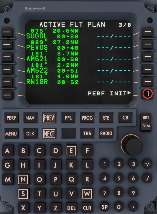
1. Press **PERF** and select **PERF INIT** (LSK 1L).
   {% endcolumn %}

{% column width="36%" %} <img src="https://2148350057-files.gitbook.io/~/files/v0/b/gitbook-x-prod.appspot.com/o/spaces%2F4zuBab090JlaOR4WgDz8%2Fuploads%2FzQ53jHmbPCFAKwzW8ndp%2Fmcdu-preflight-step-30.png?alt=media" alt="MCDU Step 30" width="100%">
{% endcolumn %}
{% endcolumns %}

## Step 31

{% columns %}
{% column width="64%" %}

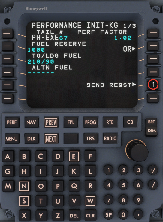
1. On **PERF INIT 1/3**, select **SEND REQST** to pull performance data from your SimBrief OFP.
   {% endcolumn %}

{% column width="36%" %} <img src="https://2148350057-files.gitbook.io/~/files/v0/b/gitbook-x-prod.appspot.com/o/spaces%2F4zuBab090JlaOR4WgDz8%2Fuploads%2Fqdq8VAV56dYKxxDLIdGH%2Fmcdu-preflight-step-31.png?alt=media" alt="MCDU Step 31" width="100%">
{% endcolumn %}
{% endcolumns %}

## Step 32

{% columns %}
{% column width="64%" %}

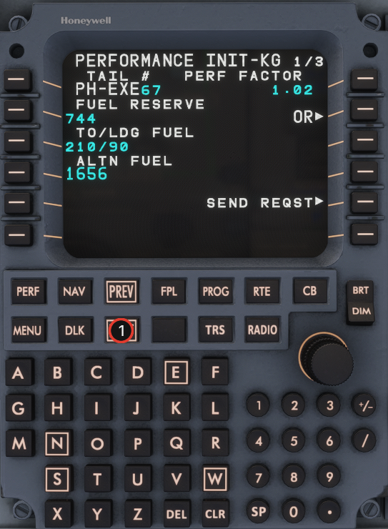
1. Press **NEXT** to **PERF INIT 2/3**.
   {% endcolumn %}

{% column width="36%" %} <img src="https://2148350057-files.gitbook.io/~/files/v0/b/gitbook-x-prod.appspot.com/o/spaces%2F4zuBab090JlaOR4WgDz8%2Fuploads%2FqE9IU2Y2eLWsVXrAKWHt%2Fmcdu-preflight-step-32.png?alt=media" alt="MCDU Step 32" width="100%">
{% endcolumn %}
{% endcolumns %}

## Step 34

{% columns %}
{% column width="64%" %}

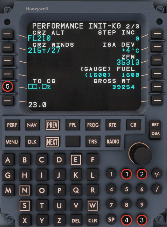
1. Enter **TO CG** from the EFB manifest (e.g. type `23.0` on the keypad).
2. Transfer the scratchpad value with the **TO CG** line-select key (LSK 5L).
   {% endcolumn %}

{% column width="36%" %} <img src="https://2148350057-files.gitbook.io/~/files/v0/b/gitbook-x-prod.appspot.com/o/spaces%2F4zuBab090JlaOR4WgDz8%2Fuploads%2FbCZ3ukA9lJ6jaM0G0OMT%2Fmcdu-preflight-step-34.png?alt=media" alt="MCDU Step 34" width="100%">
{% endcolumn %}
{% endcolumns %}

## Step 35

{% columns %}
{% column width="64%" %}

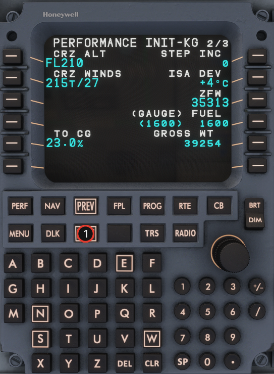
1. Press **NEXT** to **PERF INIT 3/3**.
   {% endcolumn %}

{% column width="36%" %} <img src="https://2148350057-files.gitbook.io/~/files/v0/b/gitbook-x-prod.appspot.com/o/spaces%2F4zuBab090JlaOR4WgDz8%2Fuploads%2FwGrEDpvd2Pmem6JQGEtR%2Fmcdu-preflight-step-35.png?alt=media" alt="MCDU Step 35" width="100%">
{% endcolumn %}
{% endcolumns %}

## Step 36

{% columns %}
{% column width="64%" %}

1. Press **CONFIRM INIT>** (LSK 6R, inverse white) to confirm performance initialization.
2. Without this step the vertical profile is **not** calculated — see PERF.
   {% endcolumn %}

{% column width="36%" %} <img src="https://2148350057-files.gitbook.io/~/files/v0/b/gitbook-x-prod.appspot.com/o/spaces%2F4zuBab090JlaOR4WgDz8%2Fuploads%2FEEbEKaRKH03vvnwxjohQ%2Fmcdu-preflight-step-36.png?alt=media" alt="MCDU Step 36" width="100%">
{% endcolumn %}
{% endcolumns %}

## Step 37

{% columns %}
{% column width="64%" %}

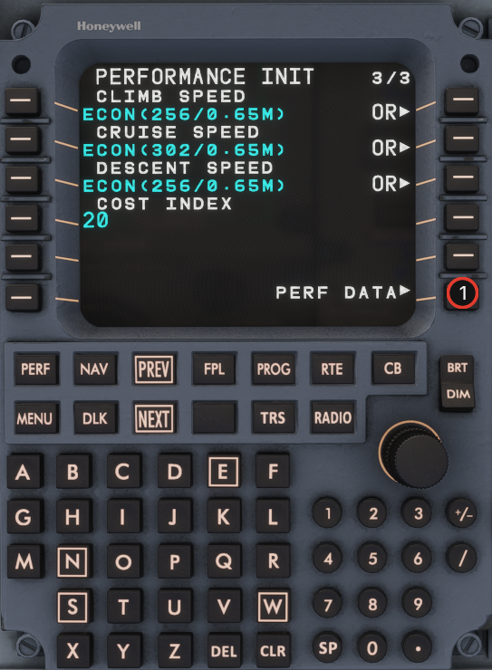
1. Select **PERF DATA>** (LSK 6R) to review the performance summary.
   {% endcolumn %}

{% column width="36%" %} <img src="https://2148350057-files.gitbook.io/~/files/v0/b/gitbook-x-prod.appspot.com/o/spaces%2F4zuBab090JlaOR4WgDz8%2Fuploads%2F8Xl8tL55mOFgCIWYyJe8%2Fmcdu-preflight-step-37.png?alt=media" alt="MCDU Step 37" width="100%">
{% endcolumn %}
{% endcolumns %}

## Step 38

{% columns %}
{% column width="64%" %}

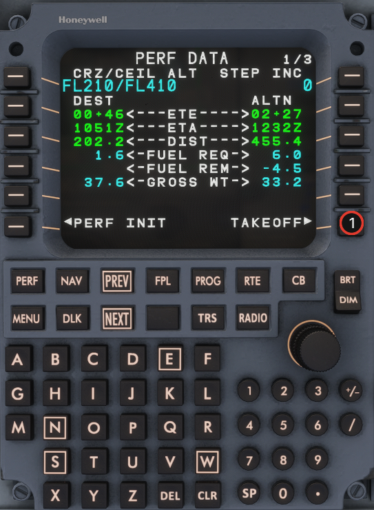
1. Select **TAKEOFF>** from the performance workflow prompts.
   {% endcolumn %}

{% column width="36%" %} <img src="https://2148350057-files.gitbook.io/~/files/v0/b/gitbook-x-prod.appspot.com/o/spaces%2F4zuBab090JlaOR4WgDz8%2Fuploads%2FP660DaN57D7uSQQsIANi%2Fmcdu-preflight-step-38.png?alt=media" alt="MCDU Step 38" width="100%">
{% endcolumn %}
{% endcolumns %}

## Step 39

{% columns %}
{% column width="64%" %}

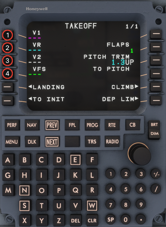
1. Enter **V1**, **VR**, **V2**, and **VFS** from the EFB manifest / loadsheet.
   {% endcolumn %}

{% column width="36%" %} <img src="https://2148350057-files.gitbook.io/~/files/v0/b/gitbook-x-prod.appspot.com/o/spaces%2F4zuBab090JlaOR4WgDz8%2Fuploads%2FYfFK5cAPKOcWBAOBTAAs%2Fmcdu-preflight-step-39.png?alt=media" alt="MCDU Step 39" width="100%">
{% endcolumn %}
{% endcolumns %}

## Step 40

{% columns %}
{% column width="64%" %}

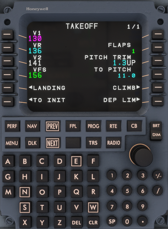
1. Preflight MCDU setup complete — you are ready for departure.
   {% endcolumn %}

{% column width="36%" %} <img src="https://2148350057-files.gitbook.io/~/files/v0/b/gitbook-x-prod.appspot.com/o/spaces%2F4zuBab090JlaOR4WgDz8%2Fuploads%2FLzEbMvoseu3OsSdN4bUX%2Fmcdu-preflight-step-40.png?alt=media" alt="MCDU Step 40" width="100%">
{% endcolumn %}
{% endcolumns %}


# Overhead Panel


# ELECTRICAL - AC

![](//cdn.document360.io/417c2d4d-fdb8-4d4d-b11d-011fe445d776/Images/Documentation/electrical-panel---ac-image-gvn9d0sg.png)

### IDG 1 and IDG 2 SELECTOR KNOBS <a href="#toc118376390" id="toc118376390"></a>

**AUTO:** This position closes the IDG contactor, connecting the IDG to the respective AC BUS. When an engine starts, the IDG will automatically come on line, powering the respective AC BUS. The previous power source is disconnected from that AC BUS.

**OFF:** Opens the IDG contactor, isolating the IDG from the respective AC BUS. IDG is tripped off-line and de-excited.

**DISC:** Must be held in this position <mark style="color:red;">for one second to mechanically disconnect the IDG. After disconnect the flight crew cannot reconnect the IDG.</mark>

<mark style="color:red;">Source Priority for the AC BUS 1 and 2: Respective IDG (Onside), APU Generator (Inside), Ground Power Unit (Outside), Opposite IDG (Cross-side).</mark>

### APU GENERATOR BUTTON <a href="#toc118376391" id="toc118376391"></a>

**PUSH IN:** Automatically connects the APU generator to the AC BUS TIE, according to the source priority.

**PUSH OUT:** Opens the APU generator contactor and isolates the APU generator from the AC BUS TIE.

![](//cdn.document360.io/417c2d4d-fdb8-4d4d-b11d-011fe445d776/Images/Documentation/electrical-panel---ac-image-ndzevioo.png)

### IDG OIL INDICATOR <a href="#toc118376392" id="toc118376392"></a>

* <mark style="color:red;">Illuminates for high oil temperature or low oil pressure (HOTLOP) indicating which IDG must be disconnected.</mark>
* <mark style="color:red;">LED will be OFF after IDG disconnection.</mark>
* <mark style="color:red;">Associated with an EICAS message.</mark>

### AC BUS TIES SELECTOR KNOB <a href="#toc118376393" id="toc118376393"></a>

**TWO OPEN:** Opens the Bus Tie Contactor 1, segregating AC BUS 1 from AC BUS 2

**AUTO:** This position controls the operation of the BTCs, according to system logic. If one of the AC power sources fails, both AC electrical networks are automatically connected by BTCs.

**ONE OPEN:** Opens the BUS TIE Contactor 2, segregating AC BUS 2 from AC BUS 1.

### GROUND POWER UNIT (GPU) BUTTON <a href="#toc118376394" id="toc118376394"></a>

**PUSH IN:** Connects the AC GPU to the AC BUS TIE, according to source priority (AVAIL -> IN USE).

**PUSH OUT**: Isolates the AC GPU from the AC BUS TIE (IN USE -> AVAIL).

**AVAIL:** AC GPU is connected <mark style="color:red;">and AC power quality requirements (voltage/amperage/frequency) are within limits.</mark>

**IN USE:** AC GPU is powering the airplane.

{% hint style="info" %}
Before disconnecting the AC GPU the push button must be pushed out. The AC GPU has to be pushed out for the next connection.
{% endhint %}


# ELECTRICAL - DC

![](//cdn.document360.io/417c2d4d-fdb8-4d4d-b11d-011fe445d776/Images/Documentation/electrical-panel--dc-image-6iw5x5rl.png)

### TRU 1 and TRU 2 TOGGLE <a href="#toc118376396" id="toc118376396"></a>

**AUTO:** Automatic operation of the electrical system. Connects TRU 1 (2) to the respective DC bus

**OFF:** Isolates TRU 1(2) from the respective DC bus

### TRU ESS SWITCH <a href="#toc118376397" id="toc118376397"></a>

**AUTO:** Automatic operation of the electrical system. Connects TRU ESS to the ESS BUS 3

**OFF:** TRU ESS is isolated from ESS BUS 3

NOTE: DC GPU supplies power to only APU START BUS. It does not charge the batteries.

![](//cdn.document360.io/417c2d4d-fdb8-4d4d-b11d-011fe445d776/Images/Documentation/electrical-panel--dc-image-71zv7mwa.png)

### BATT 1 SELECTOR KNOB <a href="#toc118376398" id="toc118376398"></a>

**ON:** Connects Battery 1 to DC ESS BUS 1

**OFF:** Power is only supplied to HOT BATT BUS 1

**HOT BATT BUS 1 powers:** Engine 1A and 2A fire extinguisher, engine fuel shutoff valve 1, hydraulic system shutoff valve 1, engine 1 oil level indication, Courtesy/Service lights fwd, DC ceiling lights.

### BATT 2 SELECTOR KNOB <a href="#toc118376399" id="toc118376399"></a>

**AUTO:** Connects Battery 2 to DC ESS BUS 2. Allows Battery 2 to power the APU START BUS during APU start.

**OFF:** Power is only supplied to the HOT BATT BUS 2

**HOT BATT BUS 2 powers:** Engine 1B and 2B fire extinguisher, engine fuel shutoff valve 2, hydraulic system shutoff valve 2, engine 2 oil level indication, refueling panel, Water and Waste controller, and CMC.

NOTES:

* Supply essential loads for 10 minutes.
* On ground if powered only by batteries for more than 5 minutes a horn will sound.
* Wait to turn the batteries off when leaving the aircraft until the APU off and APU FUEL SOV CLSD EICAS messages are displayed (approx.. 80 seconds).

### DC BUS TIES <a href="#toc118376400" id="toc118376400"></a>

**AUTO:** Allows automatic operation of the electrical system.

**OFF:** DC bus ties open.


# COCKPIT LIGHTS

![](//cdn.document360.io/417c2d4d-fdb8-4d4d-b11d-011fe445d776/Images/Documentation/cockpit-lights-panel-image-9b0ybu4j.png)

### MAIN PNL KNOB <a href="#toc118376402" id="toc118376402"></a>

**OFF:** Turns the lights off.

**BRT:** Lights full bright.

### OVHD PNL KNOB <a href="#toc118376403" id="toc118376403"></a>

**OFF:** Turns the lights off.

**BRT:** Lights full bright.

### PEDESTAL KNOB <a href="#toc118376404" id="toc118376404"></a>

**OFF:** Button/window indications remain illuminated to full bright as a default operations configuration. All other lights turned off (backlighting).

**BRT:** Lights full bright.

### ANNUNCIATOR TEST BUTTON (Momentary position) <a href="#toc118376405" id="toc118376405"></a>

* Illuminates the white/amber striped bars and caption indications verifying the lamp integrity.
* Does NOT check parking brake ON light, AC GPU Button, or Fire indications.

### DOME SWITCH <a href="#toc118376406" id="toc118376406"></a>

**ON:** Turns 2 cockpit dome lights ON.

**OFF:** Turns 2 cockpit dome lights OFF.


# ENGINE FIRE HANDLE

![](//cdn.document360.io/417c2d4d-fdb8-4d4d-b11d-011fe445d776/Images/Documentation/engine-fire-handle-image-314naadl.png)

### ENGINE FIRE HANDLE <a href="#toc118376408" id="toc118376408"></a>

<mark style="color:red;">**PULL:**</mark> <mark style="color:red;"></mark><mark style="color:red;">Closes the associated engine bleed air, fuel and hydraulic shutoff valves, and crossbleed valve.</mark>

<mark style="color:red;">**ROTATE (left or right):**</mark> <mark style="color:red;"></mark><mark style="color:red;">Discharges the A (left) or B(right) fire extinguisher bottle into the associated engine.</mark>

<mark style="color:red;">Engine Fire Indication:</mark>

* <mark style="color:red;">Engine Fire handle illuminates</mark>
* <mark style="color:red;">EICAS displays ENG (1) (2) FIRE message</mark>
* <mark style="color:red;">Master Warning triple chime and fire bell</mark>
* <mark style="color:red;">FIRE displayed on the respective engine ITT gauge</mark>
* <mark style="color:red;">Master Warning lights on glareshield illuminate</mark>


# FUEL

![](//cdn.document360.io/417c2d4d-fdb8-4d4d-b11d-011fe445d776/Images/Documentation/fuel-panel-image-2onl8t30.png)

### XFEED SELECTOR KNOB <a href="#toc118376410" id="toc118376410"></a>

**LOW 1:** Opens the crossfeed valve and automatically activates AC PUMP2, supplying fuel to both engines from the right wing tank.

**OFF:** Closes the crossfeed valve.

**LOW 2**: Opens the crossfeed valve and automatically activates AC PUMP 1, supplying fuel to both engines from the left wing tank.

Note: Setting AC PUMP 1 or 2 selector knob to any position different than AUTO overrides fuel crossfeed pumps command.

![](//cdn.document360.io/417c2d4d-fdb8-4d4d-b11d-011fe445d776/Images/Documentation/fuel-panel-image-n8wkycos.png)

### DC PUMP SELECTOR KNOB <a href="#toc118376411" id="toc118376411"></a>

**OFF:** Deactivates the DC fuel pump.

**AUTO:** Automatically operates the DC fuel pump according to the system’s logic.

**ON:** Activates the DC fuel pump.

### AC PUMP SELECTOR KNOBS <a href="#toc118376412" id="toc118376412"></a>

**OFF:** Deactivates the associated AC fuel pump.

**AUTO:** Automatically operates the associated AC fuel pump according to the system’s logic.

**ON:** Activates the associated AC fuel pump.


# PASSENGER SIGNS

![](//cdn.document360.io/417c2d4d-fdb8-4d4d-b11d-011fe445d776/Images/Documentation/passenger-signs-panel-image-51suqfje.png)

### EMER LT SELECTOR KNOB <a href="#toc118376414" id="toc118376414"></a>

OFF: Prevents all emergency lights from illuminating if electrical power is turned off or fails.

ARMED: Automatically illuminates all emergency lights if the airplane loses electrical power or if airplane electrical power is turned off.

ON: Turns on all emergency lights.

### ATTND CALL BUTTON (Momentary Position) <a href="#toc118376415" id="toc118376415"></a>

**PUSH:** Single hi/lo tone chime in passenger cabin.

### STERILE SWITCH <a href="#toc118376416" id="toc118376416"></a>

**ON:** Illuminates the sterile rainbow light in the cabin.

**OFF:** Turns off the sterile rainbow light in the cabin.

![Ein Bild, das Text, Elektronik, Kamera enthält.  Automatisch generierte Beschreibung](//cdn.document360.io/417c2d4d-fdb8-4d4d-b11d-011fe445d776/Images/Documentation/passenger-signs-panel-image-hdzd0mzv.png)

### NO ELEC DEVICES / NO SMKG SWITCH <a href="#toc118376417" id="toc118376417"></a>

**ON:** Illuminates the respective signs.

**OFF:** Turns off the respective signs.

### FSTN BELTS SWITCH <a href="#toc118376418" id="toc118376418"></a>

**ON:** Illuminates the FASTEN SEAT BELTS signs.

**OFF:** Turns off the FASTEN SEAT BELTS signs.


# FIRE EXTINGUISHER

![](//cdn.document360.io/417c2d4d-fdb8-4d4d-b11d-011fe445d776/Images/Documentation/fire-extinguisher-panel-image-1efo5aqp.png)

### FWD/AFT CARGO FIRE DETECTION/EXTINGUISHER BUTTON (Guarded) <a href="#toc118376420" id="toc118376420"></a>

<mark style="color:red;">Button illuminates if smoke is detected in the respective cargo compartment.</mark>

### FIRE DETECTION SYSTEM TEST BUTTON (Momentary position) <a href="#toc118376421" id="toc118376421"></a>

* Tests the engine fire, APU fire, and cargo smoke detection systems
* Press and hold the test button for a minimum of 3 seconds, but not more than 10 seconds if the APU is running or it will automatically shutdown the APU.
* <mark style="color:red;">Ventilation outflow valve closes – only when bleed air is being provided by the engines or the APU</mark>

![](//cdn.document360.io/417c2d4d-fdb8-4d4d-b11d-011fe445d776/Images/Documentation/fire-extinguisher-panel-image-ffe0r9a8.png)

### APU FIRE EXTINGUISHER BUTTON (Guarded) <a href="#toc118376422" id="toc118376422"></a>

* <mark style="color:red;">Illuminates in the event of a fire when APU EMER STOP button is pressed.</mark>
* <mark style="color:red;">Illumination turns OFF when the fire input from the APU fire detectors disappears.</mark>
* <mark style="color:red;">APU FIRE EXTINGUISHER button pressed:</mark>
  * <mark style="color:red;">Discharges the APU fire bottle.</mark>
  * <mark style="color:red;">Shuts down the APU through the APU FADEC</mark>
  * <mark style="color:red;">Closes the APU fuel shutoff valve (SOV)</mark>


# APU CONTROL

![](//cdn.document360.io/417c2d4d-fdb8-4d4d-b11d-011fe445d776/Images/Documentation/apu-control-panel-image-4qilf5a2.png)

### APU SELECTOR KNOB <a href="#toc118376424" id="toc118376424"></a>

**OFF:** Normal shutdown is initiated. Pneumatic power is removed immediately, electric power is removed at the end of a 1-minute cooldown. Rotating the knob back to ON during shutdown cancels the shutdown sequence.

**ON:** Normal position when running.

**START (Momentary position):** Initiates the APU start cycle.

Note: APU electrical and pneumatic are available 3 seconds after reaching 95% rpm.

![](//cdn.document360.io/417c2d4d-fdb8-4d4d-b11d-011fe445d776/Images/Documentation/apu-control-panel-image-w6bhy1ur.png)

### APU EMERGENCY STOP BUTTON <a href="#toc118376425" id="toc118376425"></a>

<mark style="color:red;">**PUSH IN:**</mark> <mark style="color:red;"></mark><mark style="color:red;">Closes the APU shutoff valve, shutting the APU down without a cool down period. White bar illuminates in the lower half of the button.</mark>

**PUSH OUT:** Normal Position.

{% hint style="info" %}
Red striped bar in the top half of the button illuminates in the event of an APU fire. When pushed in a white striped bar illuminates and the APU FIRE EXTINGUISHER button illuminates.
{% endhint %}

APU Fuel Supply:

* DC power only the DC fuel pump provides fuel to the APU.
* AC power available with engines off, the fuel is provided by the AC fuel pump 2.
* Right engine running fuel is supplied by the ejector fuel pump from the right wing tank.
* Fuel normally supplied from the right or left fuel tank through the crossfeed valve.


# WINDSHIELD WIPER

![](//cdn.document360.io/417c2d4d-fdb8-4d4d-b11d-011fe445d776/Images/Documentation/windshield-wiper-panel-image-78d7qnxu.png)

### WINDSHIELD WIPER <a href="#toc118376427" id="toc118376427"></a>

**TIMER:** Intermittent operation

**OFF:** Windshield wiper stops in the stowed position

**LOW:** Operates at a low speed

**HI:** Operates in a high speed


# EXTERNAL LIGHTS

![](//cdn.document360.io/417c2d4d-fdb8-4d4d-b11d-011fe445d776/Images/Documentation/external-lights-panel-image-8bqbeppa.png)

### NAV SWITCH <a href="#toc118376429" id="toc118376429"></a>

**ON:** Nav lights on

**OFF:** Nav lights off

### STROBE SWITCH <a href="#toc118376430" id="toc118376430"></a>

**ON:** Strobe lights on

**OFF:** Strobe lights off

### RED BCN SWITCH <a href="#toc118376431" id="toc118376431"></a>

**ON:** Red beacon on

**OFF:** Red beacon off

### LOGO SWITCH <a href="#toc118376432" id="toc118376432"></a>

**ON:** Logo lights on

**OFF:** Logo lights off

![](//cdn.document360.io/417c2d4d-fdb8-4d4d-b11d-011fe445d776/Images/Documentation/external-lights-panel-image-nlj2crm2.png)

### TAXI LIGHT SWITCHES <a href="#toc118376433" id="toc118376433"></a>

**ON:** Respective taxi light on

**OFF:** Respective taxi light off

### INSP SWITCH <a href="#toc118376434" id="toc118376434"></a>

**ON:** Wing inspection lights on

**OFF:** Wing inspection lights off

### LANDING LIGHT SWITCHES <a href="#toc118376435" id="toc118376435"></a>

**ON:** Respective landing light on

**OFF:** Respective landing light off


# HYDRAULIC

Share feedback

Thanks for sharing your feedback!

![](//cdn.document360.io/417c2d4d-fdb8-4d4d-b11d-011fe445d776/Images/Documentation/hydraulic-panel-image-fyrqowkd.png)

### ENG PUMP SHUTOFF BUTTON <a href="#toc118376437" id="toc118376437"></a>

**PUSH IN:** Closes the hydraulic shutoff valve (SOV), isolating the respective engine driven pump (EDP) from the associated hydraulic system.

**PUSH OUT:** Normal position.

### ELECTRIC HYDRAULIC PUMP SELECTOR KNOB <a href="#toc118376438" id="toc118376438"></a>

**OFF:** Turns the respective pump off.

**AUTO:** Back-up for the respective EDP.

In flight: Activates in case of

* EDP or engine fail, or
* Flaps selected > 0.

On ground: Activates in case of flaps selected >0, and

* TL set to takeoff thrust, or
* Groundspeed > 50 kts.

**ON:** Pump operates continuously, overriding system logic.

Note: ELEC PUMP 2 in AUTO: If engine 1 running and parking brake released pump turns on (Single engine taxi logic).

![](//cdn.document360.io/417c2d4d-fdb8-4d4d-b11d-011fe445d776/Images/Documentation/hydraulic-panel-image-xwwdth3g.png)

### PTU (POWER TRANSFER UNIT) KNOB <a href="#toc118376439" id="toc118376439"></a>

**OFF:** PTU is turned off.

**AUTO:** Allows the PTU to operate automatically, according to hydraulic system logic.

**ON:** Operates continuously, overriding system logic.

### HYDRAULIC SYSTEM 3 SELECTOR KNOBS <a href="#toc118376440" id="toc118376440"></a>

**OFF:** Turns the respective electrical pump off.

**ON:** Turns the respective electrical pump on. 3B overrides system logic.

**AUTO (3B):** Turns 3B on automatically if AC Electric Pump 3A fails.

{% hint style="info" %}
The PTU does not work on the ground.
{% endhint %}

<mark style="color:red;">Note: HYDRAULIC SYSTEM 3A pump is powered by the AC ESS BUS (Electrical Emergency).</mark>


# PRESSURIZATION

![](https://cdn.document360.io/417c2d4d-fdb8-4d4d-b11d-011fe445d776/Images/Documentation/pressurization-panel-image-6jvxlgka.png)

### CABIN ALT SELECTOR KNOB

**DOWN (Momentary action):** Closes the outflow valve manually.

**STOP:** Normal position.

**UP (Momentary action):** Opens the outflow valve manually.

### MODE SELECTOR KNOB

**MAN:** Manual control of the outflow valve. No automatic cabin depressurization on the ground after landing.

**AUTO:** Automatic operation, changes between the different pressurization modes.

**LFE CTRL:** Allows manual input of the landing field elevation. Pressurization remains in automatic CPCS control. FMS-derived LFE is shown in green. Manually selected LFE is shown with a cyan **M** in front of the altitude readout.

{% hint style="info" %}
If no destination airport is in the FMS, LFE defaults to 0 ft until you set it manually in LFE CTRL.
{% endhint %}

![](https://cdn.document360.io/417c2d4d-fdb8-4d4d-b11d-011fe445d776/Images/Documentation/pressurization-panel-image-fl6qj9dc.png)

### DUMP BUTTON

**PUSH IN:** CPCS system operates automatically

**PUSH OUT:** Returns the system to normal operation.

Note: Not available in manual mode. If pushed in while in manual mode both recirculation fans and packs are turned off.

### LFE SELECTOR KNOB

**DOWN (Momentary action):** Decreases LFE in 100 ft increments.

**STOP:** Normal position.

**UP (Momentary position):** Increases the LFE in 100 ft increments.

Note: Only works when the MODE selector knob is in LFE CTRL.

![](https://cdn.document360.io/417c2d4d-fdb8-4d4d-b11d-011fe445d776/Images/Documentation/pressurization-panel-image-dj6ji9z2.png)


# ICE PROTECTION

![](//cdn.document360.io/417c2d4d-fdb8-4d4d-b11d-011fe445d776/Images/Documentation/windshield-heating--ice-protection-panel-image-6etomjo0.png)

### WINDSHIELD HEATING (1) (2) BUTTON <a href="#toc118376447" id="toc118376447"></a>

**PUSH IN:** activates the respective windshield heating system. <mark style="color:red;">Only operates if there are at least 2 AC electrical sources. If only single AC power source is available only the left windshield heat is powered.</mark>

**PUSH OUT:** Deactivates the respective windshield heating system.

### ICE PROTECTION ENGINE (1) (2) BUTTON <a href="#toc118376448" id="toc118376448"></a>

**PUSH IN:** Automatic operation. Engine cowls are heated with high stage bleed from the respective engine.

**PUSH OUT:** Deactivates the respective engine anti-ice system.

![](//cdn.document360.io/417c2d4d-fdb8-4d4d-b11d-011fe445d776/Images/Documentation/windshield-heating--ice-protection-panel-image-bgkam3h9.png)

### WING ICE PROTECTION BUTTON <a href="#toc118376449" id="toc118376449"></a>

**PUSH IN:** Automatic operation. Allows wing anti-ice protection to operate according to the ice protection mode selector setting or MCDU setting. If 1 bleed air or one engine fails, xbleed valve automatically opens and uses opposite bleed for both wings.

**PUSH OUT:** Deactivates the wing anti-ice system.

### ICE PROTECTION MODE SELECTOR KNOB <a href="#toc118376450" id="toc118376450"></a>

**AUTO:** If an icing condition is detected during flight, the ice detectors command the wing and engine anti-ice valves to open and remain activated for 2 minutes after the icing condition is no longer detected.

* <mark style="color:red;">For taxi out and takeoff, anti-icing operation must be set in the MCDU.</mark>
* For taxi in, mode selector knob must be selected to ON if icing is anticipated or encountered.

**ON:**

* Inflight: Overrides system logic, activating the anti-ice system
* Ground: Activates the anti-ice on the ground.
  * Engine anti-ice whenever an engine is running
  * Wing anti-ice at wheel speed above 40kts

### ICE PROTECTION TEST SELECTOR KNOB <a href="#toc118376451" id="toc118376451"></a>

**OFF:** Spring-loaded position. Normal position.

<mark style="color:red;">Wing anti-ice system tests itself during flight 10min after takeoff or at 10.000ft AGL, whichever occurs first.</mark>

* <mark style="color:red;">EICAS message A-I WING VLV OPEN will be displayed</mark>


# AIR COND / PNEUMATIC

Share feedback

Thanks for sharing your feedback!

![](//cdn.document360.io/417c2d4d-fdb8-4d4d-b11d-011fe445d776/Images/Documentation/air-cond--pneumatic-panel-image-5zs8xlp6.png)

### RECIRC BUTTON <a href="#toc118376453" id="toc118376453"></a>

**PUSH IN:** Allows automatic operation by the AMS. Turns on both recirculation fans, according to system logic.

**PUSH OUT:** Turns off both recirculation fans.

### PACK (1) (2) BUTTON <a href="#toc118376454" id="toc118376454"></a>

**PUSH IN:** Allows automatic operation by the AMS. Opens the respective pack flow control valve.

**PUSH OUT:** Manually closes the respective pack flow control valve.

<mark style="color:red;">NOTE: During first engine start, Emergency Ram Air Valve Built-In Test (BIT) commands PACK 1 OFF.</mark>

### BLEED (1) (2) BUTTON <a href="#toc118376455" id="toc118376455"></a>

**PUSH IN:** Allows automatic operation by the AMS. Commands the respective engine bleed valves, according to system logic.

**PUSH OUT:** Manually closes the engine bleed valves.

![](//cdn.document360.io/417c2d4d-fdb8-4d4d-b11d-011fe445d776/Images/Documentation/air-cond--pneumatic-panel-image-gubgukq7.png)

### CKPT TEMPERATURE SELECTOR <a href="#toc118376456" id="toc118376456"></a>

Controls cockpit temperature relative to the knob position.

### PAX CABIN TEMPERATURE SELECTOR <a href="#toc118376457" id="toc118376457"></a>

Controls passenger cabin temperature relative to the knob position.

<mark style="color:red;">**ATTND position:**</mark> <mark style="color:red;"></mark><mark style="color:red;">Enables the flight attendant panel(s) to control the cabin temperature. An “ENABLED” led turns on in the flight attendant panel(s) indicating they have control of the temperature.</mark>

### XBLEED BUTTON <a href="#toc118376458" id="toc118376458"></a>

**PUSH IN:** Allows automatic operation by the AMS. This position opens the cross-bleed valve, according to system logic.

**PUSH OUT**: Manually closes the cross-bleed valve.

### BLEED APU BUTTON <a href="#toc118376459" id="toc118376459"></a>

**PUSH IN:** Allows automatic operation by the AMS. Commands the APU bleed valve, according to system logic.

**PUSH OUT:** Closes the APU bleed valve.


# PASSENGER OXYGEN

Share feedback

Thanks for sharing your feedback!

![](//cdn.document360.io/417c2d4d-fdb8-4d4d-b11d-011fe445d776/Images/Documentation/passenger-oxygen-panel-image-sjnr4jy9.png)

### MASK DEPLOY SELECTOR KNOB <a href="#toc118376461" id="toc118376461"></a>

<mark style="color:red;">OFF: Disables automatic deployment of passenger oxygen masks.</mark>

<mark style="color:red;">AUTO: Automatically deployed when the cabin altitude is between 14.000ft to 14.750ft.</mark>

<mark style="color:red;">OVRD: Deploys the passenger oxygen masks regardless of cabin altitude.</mark>

### MASKS DEPLOYED LIGHT <a href="#toc118376462" id="toc118376462"></a>

<mark style="color:red;">An ON light illuminates, indicating that the passenger and flight attendant oxygen masks have been deployed.</mark>

<mark style="color:red;">When the passenger masks doors are commanded open the FASTEN SEAT BELT and the NO SMOKING signs turn on regardless of the switch position.</mark>


# GND PROX TERR INHIB AND EMERG/PRKG BRAKE

![](https://cdn.document360.io/417c2d4d-fdb8-4d4d-b11d-011fe445d776/Images/Documentation/gnd-prox-terr-inhib-and-emergprkg-brake-panel-image-f0x5fyym.png)

#### GND PROX TERR INHIB BUTTON <a href="#toc118376654" id="toc118376654"></a>

* When pushed in, inhibits EGPWS and thus avoids unwanted terrain alerts in airports not covered by EGPWS database.

#### EMERG/PRKG BRAKE LIGHT <a href="#toc118376655" id="toc118376655"></a>

* ON: Illuminates when the emergency/parking brake is actuated and there is hydraulic pressure on the brake line.


# Main Panel


# Primary Flight Display (PFD)


# SPEEDS

![](//cdn.document360.io/417c2d4d-fdb8-4d4d-b11d-011fe445d776/Images/Documentation/primary-flight-display-pfd-image-bnnk89xa.png)

### SELECTED AIRSPEED READOUT <a href="#toc118376512" id="toc118376512"></a>

Displays speed/mach values.

**MAGENTA:** Automatically set by the FMS

**CYAN:** Manually entered by the flight crew.

### V2 SPEED (2) <a href="#toc118376513" id="toc118376513"></a>

Takeoff safety speed

### VR SPEED (R) <a href="#toc118376514" id="toc118376514"></a>

Takeoff rotation speed

### V1 SPEED (1) <a href="#toc118376515" id="toc118376515"></a>

Takeoff decision speed

**AIRSPEED TRANSITION:** Airspeed transitions automatically between IAS and Mach and vice versa at approximately 29.000 ft.

![](//cdn.document360.io/417c2d4d-fdb8-4d4d-b11d-011fe445d776/Images/Documentation/primary-flight-display-pfd-image-am56ti8y.png)

### VSPEED Bugs <a href="#toc118376516" id="toc118376516"></a>

Preview mode displays in the lower portion of the airspeed tape. VSPEEDS are entered in the MCDU. When no valid VSPEED data is available and the aircraft is on the ground cyan dashes are displayed.

![](//cdn.document360.io/417c2d4d-fdb8-4d4d-b11d-011fe445d776/Images/Documentation/primary-flight-display-pfd-image-zzc3u1mf.png)

### AIRSPEED ROLLING DIGITS <a href="#toc118376517" id="toc118376517"></a>

**GREEN:** Normal range.

**AMBER** Airspeed trend vector is reaching the VMO/MMO or it is at amber low speed awareness tape or the actual airspeed is at amber low speed awareness tape.

**RED INVERSE VIDEO:** Airspeed trend vector or actual airspeed is at red low speed awareness tape or at VMO/MMO barber pole.

### LOW SPEED AWARENESS (LSA) TAPE <a href="#toc118376518" id="toc118376518"></a>

Indicates the margin to the stick shaker speed. It rises from the bottom of the speed tape and has two colored ranges.

![](//cdn.document360.io/417c2d4d-fdb8-4d4d-b11d-011fe445d776/Images/Documentation/primary-flight-display-pfd-image-yzrxy0oi.png)

### SELECTED MACH READOUT <a href="#toc118376519" id="toc118376519"></a>

Displays speed/mach values.

**MAGENTA:** Automatically set by the FMS.

**CYAN:** Manually entered by the flight crew.

### SELECTED AIRSPEED BUG <a href="#toc118376520" id="toc118376520"></a>

**MAGENTA:** Displayed at the FMS airspeed target when an FMS mode is valid.

**CYAN:** Displayed at the Manual mode airspeed target.

### MACH AIRSPEED DIGITAL DISPLAY <a href="#toc118376521" id="toc118376521"></a>

Mach digital display of the current airspeed is displayed followed by an “M” label.

### VMO/MMO BARBER POLE <a href="#toc118376522" id="toc118376522"></a>

Displayed when the VMO/MMO is within the viewable range and covers speeds at or above VMO/MMO.

![](//cdn.document360.io/417c2d4d-fdb8-4d4d-b11d-011fe445d776/Images/Documentation/primary-flight-display-pfd-image-ou74cdcn.png)

### VAC SPEED (AC) <a href="#toc118376523" id="toc118376523"></a>

Approach climb speed

### VF SPEED (F) <a href="#toc118376524" id="toc118376524"></a>

Flap retraction speed

### VAP SPEED (AP) <a href="#toc118376525" id="toc118376525"></a>

Approach speed

### VRF SPEED (RF) <a href="#toc118376526" id="toc118376526"></a>

Reference speed

### GREEN DOT <a href="#toc118376527" id="toc118376527"></a>

Provides a margin of 1.3g over stick shaker speed. <mark style="color:red;">Does account for ice, however it is invalid above FL200 with the ice EICAS message displayed.</mark>

### VFS SPEED (FS) <a href="#toc118376528" id="toc118376528"></a>

Takeoff final segment speed.


# FLIGHT MODE ANNUNCIATORS (FMA)

### AUTOTHROTTLE ANNUNCIATIONS ON FMA

**Left Column:**

* The AT mode annunciations displayed on the Flight Mode Annunciation display (FMA) are:
  * Top row indicates autothrottle engagement mode
  * Bottom row indicates autothrottle armed mode

**Right Column:**

* Depicts whether the Autothrottle is engaged or disengaged.

### AUTOPILOT ENGAGE (AP/TCS) ANNUNCIATOR

### AUTOPILOT/AUTOTHROTTLE SOURCE SELECTION

PFD source that currently supplies the references (primary NAV source and selected airspeed reference) for FGCS autothrottle or flight director operation. It is controlled by the SRC button the Glareshield Panel.

### APPROACH STATUS INDICATION

Approach armed status is white, left of the source selector. Approach engaged status is green, right of the source selector.

| Annunciator     | Color         | Meaning                                                |
| --------------- | ------------- | ------------------------------------------------------ |
| **APPR 1**      | White / Green | CAT I capable — armed / engaged                        |
| **APPR 1 ONLY** | White / Amber | CAT I is the only available approach mode              |
| **APPR 2**      | White / Green | CAT II capable — armed / engaged                       |
| **APPR 2 ONLY** | White / Amber | CAT II armed/engaged and it is the only available mode |
| **AUTOLAND 1**  | White / Green | Autoland 1 (Cat IIIa) armed / engaged                  |
| **AUTOLAND 2**  | White / Green | Autoland 2 (Cat IIIb) armed / engaged — E170 only      |
| **NO AUTOLAND** | Red           | Autopilot still engaged after AUTOLAND 1/2 was lost    |
| **L/VNAV**      | White         | FMS LNAV/VNAV approach armed                           |
| **LPV**         | White         | LPV approach armed                                     |

Armed modes flash reverse video for 5 seconds, then remain steady.

**CAT I (APPR 1)**

* Minimums set to **BARO** (DA).
* LOC and GS armed or active.
* Engages when LOC and GS are active and radio altitude is below 1,500 ft (or RA invalid).
* Disconnect AP before 200 ft AGL on a CAT I approach.

**CAT II (APPR 2)**

Armed when all of the following are met:

* Both PFDs set minimums to **RA** (and the same RA value).
* Both NAV receivers on the ILS frequency and course.
* Dual valid NAV / independent IRS and air data (no relevant miscompares).
* LOC and GS armed or active.
* Steep approach not armed or engaged.
* Radio altitude not below 800 ft (capability freeze).
* Airplane is approach-2 capable (valid RA, dual PFDs, etc.).

If APPR 2 is not capable, **APPR 2 NOT AVAIL** is posted on CAS.

**AUTOLAND**

Autoland is an option, enabled on the MCDU **OPR CONFIG** page.

* **AUTOLAND 1** — E170/E175/E190/E195.
* **AUTOLAND 2** — E170 only, and autobrake must be armed.

Typical extra requirements versus APPR 2: autoland option ON, autopilot engaged, yaw damper on, independent NAV sources on each side.

If autoland was engaged and the configuration is lost, **NO AUTOLAND** is shown in red.

{% hint style="info" %}
AUTOLAND 1/2 is approach-status logic on the FMA. It is not a substitute for a real-world Cat III autoland qualification.
{% endhint %}

### AUTOPILOT

* Autopilot disengagement:
  * Either AP/TRIM DISC button is pushed.
  * AP button on the Glareshield Panel is pushed
  * Any manual pitch trim is activated
  * Stick shaker activated
  * Wi<mark style="color:red;">ndshear escape guidance is activated</mark>
  * A pilot input contrary to the autopilot is made on the controls.
* Autopilot will remain engaged in the event of an engine failure.
* Default Modes for the autopilot are: ROLL and FPA.

### LATERAL FLIGHT DIRECTOR MODES

### VERTICAL FLIGHT DIRECTOR MODES

**Default Modes:**

* Roll Hold (ROLL) is the default lateral mode (roll hold, wings level, and heading hold).
* When the autopilot is engaged without any modes being selected, ROLL is automatically engaged.
* When a vertical mode is selected without a lateral mode, the default ROLL mode is activated. The mode is displayed above the attitude indicator on the PFD
* Flight Path Angle (FPA) mode is the default vertical mode.

Magenta FMS modes (**FLCH**, **PTH**, **ASEL**, **ALT**, **GP**) are shown when VNAV is active. Automatic **OVSP** is shown when overspeed protection is active. **GA** is shown during go-around.

### WINDSHEAR

* <mark style="color:red;">Activated between 10 ft and 1.500 ft radio altitude.</mark>
* <mark style="color:red;">“WSHEAR” label displays on the PFD</mark>
* <mark style="color:red;">Windshear Caution: Increasing headwind and up drafts. Amber flag and aural alert “CAUTION, WINDSHEAR”.</mark>
* <mark style="color:red;">Windshear Warning: Decreasing headwind (or increasing tailwind) and down drafts. Red flag and aural alert “WINDSHEAR, WINDSHEAR, WINDSHEAR”.</mark>
* <mark style="color:red;">Autopilot automatically disconnects when windshear guidance is activated.</mark>
* <mark style="color:red;">Windshear alerting will last until 1.500 ft AGL or clear of windshear.</mark>
* <mark style="color:red;">Windshear alerting system will not function if both radar altimeters and/or EGPWS is inoperative.</mark>

### FLIGHT DIRECTOR GUIDANCE CUE IN TAKEOFF MODE

* Magenta vertical and horizontal bar.
* Displayed when the TO flight director mode is active.
* Takeoff guidance crossbars maintain extended runway centerline and pitch attitude based on appropriate configuration.


# ALTITUDES

### SELECTED ALTITUDE DIGITAL READOUT <a href="#toc118376536" id="toc118376536"></a>

* Displays altitude rounded to 100 ft.
* Displays cyan dashes on ground power-up.
* Altitude alerter sounds when the aircraft is within 1.000 ft of selected altitude.
* After altitude capture, when the aircraft departs more than 200ft from the selected altitude, altitude alerter sounds.

### METRIC SELECTED ALTITUDE READOUT <a href="#toc118376537" id="toc118376537"></a>

* Alternately displayed or removed by the PUSH FT-M switch that is integral on the ALT knob.
* An M indicates meters with a resolution of 50 meters.

### ALTITUDE ROLLING DIGITS DISPLAY <a href="#toc118376538" id="toc118376538"></a>

* Actual altitude rolled to a resolution of 1 foot but labeled every 20 feet.
* For negative altitudes a (-) is displayed in the place of the thousands digit.
* The ten-thousands, thousands and hundreds digits are taller.
* Altitudes above 0 but less than 10.000 ft have a green/black hashed box symbol that replaces the ten-thousands digit.

### METRIC ALTITUDE DISPLAY <a href="#toc118376539" id="toc118376539"></a>

* Alternately displayed or removed from display by the PUSH FT-M switch that is integral to the ALT knob.
* Current altitude in meters is displayed to a resolution of 5 meters. An M indicates meters.

### SELECTED ALTITUDE BUG <a href="#toc118376540" id="toc118376540"></a>

* Corresponds to the altitude value set in the altitude alert select digital display.
* When the selected altitude is off the displayed range, half of the bug remains on the top or bottom of the scale to indicate the direction to the selected altitude.

### ALTITUDE TREND VECTOR <a href="#toc118376541" id="toc118376541"></a>

* White thermometer starting at the altitude reference line and extends to the altitude the aircraft is at in 6 seconds, based on current vertical speed.

### ALTITUDE TAPE <a href="#toc118376542" id="toc118376542"></a>

* White tick marks are at 100-foot increments, except the white chevrons are at the 500-foot increments.
* When barometric altitude status or BARO correction data is invalid, altitude data is removed and a X is placed over the entire altitude tape area.

### BAROMETRIC ALTITUDE BOX <a href="#toc118376543" id="toc118376543"></a>

* Value is adjusted with BARO SET knob on the guidance panel.
* When the PUSH STD button on the BARO SET knob is pushed the altimeter setting window changes to STD and the correction is set to 29.92 inHg or 1013 hPa.

### SELECTED VERTICAL SPEED READOUT and BUG <a href="#toc118376544" id="toc118376544"></a>

* Displayed when VS is the active vertical flight director mode.
* Vertical speed is manually entered by using the VS wheel when the FGCS is in VS mode.
* Cyan filled bug is displayed on the vertical speed scale and is positioned at the selected vertical speed readout value.
* Cyan arrows above or below the display indicate the aircraft must climb or descend to attain the target vertical speed.

### VERTICAL SPEED SCALE <a href="#toc118376545" id="toc118376545"></a>

* Green pointer indicates the vertical speed on the scale.
* When pressure altitude data is invalid, display shows X

### VERTICAL SPEED DIGITAL READOUT <a href="#toc118376546" id="toc118376546"></a>

* Displays digital vertical speed.
* If TCAS RA is active, vertical speed readout is removed.
* At vertical speeds greater than +- 9.900 FPM, when the pressure altitude data received is invalid or when the altitude rate data is invalid the readout displays ----

### AVOIDANCE ZONE <a href="#toc118376547" id="toc118376547"></a>

<mark style="color:red;">Red trapezoid indicating the pitch that should be left to prevent collision with other aircrafts.</mark>

### FLY-TO-ZONE <a href="#toc118376548" id="toc118376548"></a>

<mark style="color:red;">Green rectangle indicating the pitch that should be followed to prevent collision with other aircrafts.</mark>

### RADIO ALTITUDE READOUT <a href="#toc118376549" id="toc118376549"></a>

* Only displayed when radio altitude is valid and less than 2.500 ft.
* RALT 1 is displayed on PFD 1, and RALT 2 is displayed on PFD 2.
* <mark style="color:red;">When one radio altimeter is invalid, the system automatically selects the other radio altimeter. Both displays turn amber and a CAS message is posted for the non-valid radio altitude system.</mark>
* <mark style="color:red;">When a miscompare occurs between system 1 and 2, an RA source data miscompare annunciator is displayed above the digital readout box (RA).</mark>
* <mark style="color:red;">When the radio altitude is invalid in both RA systems, the radio altitude readout is removed and is displayed. Corresponding CAS message is posted indicating both radio altitude systems have failed (-RA-).</mark>

### SELECTED MINIMUM RA/BARO ALTITUDE READOUT and BUG <a href="#selected-minimum-rabaro-altitude-readout-and-bug" id="selected-minimum-rabaro-altitude-readout-and-bug"></a>

* Set using the MINIMUMS rotary knob when BARO is selected on the MINIMUMS RA/BARO select switch.
* If additional counterclockwise clicks occur after the display reads 0 it will display OFF. After 5 seconds display is removed from view.
* Selected BARO altitude bug (with a horizontal L that sticks out from the left edge of the altitude tape).
* When barometric altitude is equal to or less than the approach minimums set value the bug and MIN annunciator turn amber.
* BARO minimum bug has priority over the trend vector.


# MARKER BEACONS

### MARKER BEACONS <a href="#marker-beacons" id="marker-beacons"></a>

![](https://cdn.document360.io/417c2d4d-fdb8-4d4d-b11d-011fe445d776/Images/Documentation/primary-flight-display-pfd-image-qzu1v176.png)

Located in the upper right corner:

![](https://cdn.document360.io/417c2d4d-fdb8-4d4d-b11d-011fe445d776/Images/Documentation/primary-flight-display-pfd-image-xxa4z8pf.png)


# FLIGHT PATH / ATTITUDE INDICATIONS

### FLIGHT PATH VECTOR (FPV)

* Consists of a green aircraft symbol that indicates the current flight path angle in reference to the horizon line.
* <mark style="color:red;">FPV turns red when TCAS RA is active and the FPV is in the Avoidance Zone.</mark>
* <mark style="color:red;">FPV is removed when excessive pitch is exceeded.</mark>

### FLIGHT PATH VECTOR SPEED ERROR TAPE

* Green tape that rises or descends from the left wing of the FPA symbol.
* Represents the difference between the selected airspeed and the current airspeed.
* Down indicates current airspeed is less than the selected airspeed, and up indicates more.

### FLIGHT PATH VECTOR ACCELERATION POINTER

* Displayed when FD is selected and gives an analog indication of acceleration and deceleration rate along the flight path.
* Moves up for increasing values of flight path acceleration and moves down for decreasing values of flight path acceleration.

![](https://cdn.document360.io/417c2d4d-fdb8-4d4d-b11d-011fe445d776/Images/Documentation/primary-flight-display-pfd-image-2gv9w7el.png)

### ATTITUDE REFERENCE AIRCRAFT SYMBOL

* Aircraft symbol is centered and always points to the top of the display. The background rotates around it.
* Displayed at all times and is used with the pitch tape to reflect aircraft pitch and roll attitude in relation to the horizon line.

### HORIZON LINE

* Based on the current aircraft pitch and roll attitude.
* When the horizon line and the attitude reference aircraft symbol are overlaid, the aircraft is in a level pitch attitude.

![](https://cdn.document360.io/417c2d4d-fdb8-4d4d-b11d-011fe445d776/Images/Documentation/primary-flight-display-pfd-image-mr9v7iuy.png)

### FLIGHT DIRECTOR GUIDANCE CUE

* Displayed as a magenta diamond with short wings.
* Fits within the flight path vector symbol.
* If pitch or roll command data is invalid, the flight director guidance cue is removed.

Flight Director automatically displays:

* TOGA button actuation
* Autopilot is activated
* <mark style="color:red;">Windshear detection</mark>

![](https://cdn.document360.io/417c2d4d-fdb8-4d4d-b11d-011fe445d776/Images/Documentation/primary-flight-display-pfd-image-kxag4wqz.png)

### PITCH LIMIT INDICATOR (PLI)

The PLI is a pitch-based cue between stick-shaker angle of attack and current airplane angle of attack. It is shown on the PFD attitude display.

**DISPLAY LOGIC**

* Airplane airborne.
* Radio altitude greater than 200 ft.
* Calibrated airspeed at or below 1.2 Vs (low-speed / high-AOA regime).

**COLORS**

* **Green** — more than 5° remaining to stick shaker.
* **Amber** — 5° or less remaining to stick shaker.
* **Red** — stick shaker is active.

The PLI is removed above the speed/AOA gate and below 200 ft RA.

<br>

### &#x20;<a href="#toc118376560" id="toc118376560"></a>

![Pitch Limit Indicator](https://cdn.document360.io/417c2d4d-fdb8-4d4d-b11d-011fe445d776/Images/Documentation/primary-flight-display-pfd-image-v7otuv1g.png)

### ROLL SCALE

* Tick marks are located every 10 degrees up to 30 degrees.
* Inverted triangles are displayed at 0 and 45 degrees of roll.

### ROLL POINTER AND SLIP/SKID INDICATION

* The triangle is the roll pointer.
* Bottom half of the roll pointer is used as a slip/skid indicator.
  * Lower portion of the triangle moves left or right to show the slip or skid condition

![Roll pointer](https://cdn.document360.io/417c2d4d-fdb8-4d4d-b11d-011fe445d776/Images/Documentation/primary-flight-display-pfd-image-wnz9y2dt.png)

### LOW BANK LIMIT ARC

* <mark style="color:red;">Helps the pilot to fly with low bank angles during turns.</mark>

![](https://cdn.document360.io/417c2d4d-fdb8-4d4d-b11d-011fe445d776/Images/Documentation/primary-flight-display-pfd-image-6fpjxapv.png)

### FLIGHT PATH ANGLE (FPA)

* Indicates the current flight path in reference to the horizon line
* Cyan color.


# HORIZONTAL SITUATION INDICATOR (HSI)

![](https://cdn.document360.io/417c2d4d-fdb8-4d4d-b11d-011fe445d776/Images/Documentation/primary-flight-display-pfd-image-fj96qpi2.png)

### HORIZONTAL SITUATION INDICATOR (HSI) DISPLAYS AND ANNUNCIATORS <a href="#toc118376570" id="toc118376570"></a>

* Heading display on the HSI has 3 selectable modes: Full compass, Arc, and Map mode.
* <mark style="color:red;">Modes are selected by pushing the HSI button.</mark>

### FULL COMPASS MODE <a href="#toc118376571" id="toc118376571"></a>

* Displayed on initialization.
* 360-degree compass view
* Present heading is indicated by a fixed lubber ![](https://cdn.document360.io/417c2d4d-fdb8-4d4d-b11d-011fe445d776/Images/Documentation/primary-flight-display-pfd-image-z6x7q47h.png) line at the top of the heading scale with a digital heading readout directly above the lubber line.

### ARC MODE <a href="#toc118376572" id="toc118376572"></a>

* <mark style="color:red;">90 degrees of compass view.</mark>
* <mark style="color:red;">Weather is displayed when the WX button is pushed.</mark>
* <mark style="color:red;">When the heading bug goes beyond the display range</mark> ![](https://cdn.document360.io/417c2d4d-fdb8-4d4d-b11d-011fe445d776/Images/Documentation/primary-flight-display-pfd-image-z7ww0l6r.png)<mark style="color:red;">is displayed and shows the shortest direction to the heading select bug.</mark>

### MAP MODE <a href="#toc118376573" id="toc118376573"></a>

* <mark style="color:red;">90 degrees of compass view.</mark>
* <mark style="color:red;">Weather is displayed when the WX button is pushed.</mark>
* <mark style="color:red;">Flight plans are displayed</mark>
* <mark style="color:red;">Cannot be used for preview mode.</mark>

![Ein Bild, das Text, Gerät, schwarz, verschieden enthält.  Automatisch generierte Beschreibung](https://cdn.document360.io/417c2d4d-fdb8-4d4d-b11d-011fe445d776/Images/Documentation/primary-flight-display-pfd-image-ru8m5lvq.png)

### SELECTED HEADING DIGITAL READOUT AND BUG <a href="#toc118376574" id="toc118376574"></a>

* Displays the digital value for the aircraft selected heading.
* Cyan heading select bug is positioned by rotating the HDG SEL knob.
* Pushing the PUSH SYNC button on the HDG SEL knob synchronizes the heading bug and readout to the current aircraft heading.
* <mark style="color:red;">When the aircraft selected heading (or the referenced aircraft heading) is invalid, the bug is removed, and digital readout is replaced with</mark> ![](https://cdn.document360.io/417c2d4d-fdb8-4d4d-b11d-011fe445d776/Images/Documentation/primary-flight-display-pfd-image-jdwfqd4t.png)

![](https://cdn.document360.io/417c2d4d-fdb8-4d4d-b11d-011fe445d776/Images/Documentation/primary-flight-display-pfd-image-nsu8ipfu.png)

### DRIFT ANGLE BUG <a href="#toc118376575" id="toc118376575"></a>

* <mark style="color:red;">Represented by an inverted solid white triangle displayed on the outside edge of the heading scale.</mark>
* <mark style="color:red;">The difference between the aircraft heading and the aircraft ground track is the drift angle.</mark>
* <mark style="color:red;">The drift angle bug is placed on the edge of the heading scale and aligned to the drift angle with respect to the lubber line.</mark>
* <mark style="color:red;">When the drift angle is 0 degrees, the drift bug fits inside the heading bracket notch.</mark>

![Ein Bild, das Text, Anzeigetafel enthält.  Automatisch generierte Beschreibung](https://cdn.document360.io/417c2d4d-fdb8-4d4d-b11d-011fe445d776/Images/Documentation/primary-flight-display-pfd-image-ql341w9z.png)

### PRIMARY NAV SOURCE ANNUNCIATOR <a href="#toc118376576" id="toc118376576"></a>

* Selected using the **V/L** or **FMS** buttons.
* The **V/L**(VOR/LOC) button selects the available SRN (short-range navigation) source, displayed in green.
  * The associated annunciators are ![](https://cdn.document360.io/417c2d4d-fdb8-4d4d-b11d-011fe445d776/Images/Documentation/primary-flight-display-pfd-image-g1syspd5.png)
* The **FMS**button selects FMS as the source, displayed in magenta.
  * With dual FMS systems installed the identifier will show ![](https://cdn.document360.io/417c2d4d-fdb8-4d4d-b11d-011fe445d776/Images/Documentation/primary-flight-display-pfd-image-82pfxjig.png)
* <mark style="color:red;">When both sides have the same NAV source selected, digital readout for all information turns amber.</mark>

### PRIMARY NAV DISTANCE IDENTIFIER <a href="#toc118376577" id="toc118376577"></a>

* Displays the NAV source station identifier.
* The next magenta TO waypoint identifier is displayed.

### PRIMARY NAV DISTANCE READOUT <a href="#toc118376578" id="toc118376578"></a>

* Distances of 100 NM or more, the digits are displayed with 1 NM resolution
* Distances of less than 100 NM, the digits are displayed with 0.1 NM resolution

### PRIMARY NAV ESTIMATED TIME ENROUTE <a href="#toc118376579" id="toc118376579"></a>

* Time is always displayed in minutes.

![Ein Bild, das Text, Gerät, Anzeige, Messanzeige enthält.  Automatisch generierte Beschreibung](https://cdn.document360.io/417c2d4d-fdb8-4d4d-b11d-011fe445d776/Images/Documentation/primary-flight-display-pfd-image-aol0rro3.png)

### HEADING SOURCE ANNUNCIATORS <a href="#toc118376580" id="toc118376580"></a>

* <mark style="color:red;">Selected by the IRS reversion buttons.</mark>
* <mark style="color:red;">Not displayed when the on-side IRS source and magnetic heading are selected.</mark>

![](https://cdn.document360.io/417c2d4d-fdb8-4d4d-b11d-011fe445d776/Images/Documentation/primary-flight-display-pfd-image-du7nyt3g.png)

### COURSE SELECT/DESIRED TRACK POINTER AND READOUT <a href="#toc118376581" id="toc118376581"></a>

* Green for VOR and LOC navigation and the label is ![](https://cdn.document360.io/417c2d4d-fdb8-4d4d-b11d-011fe445d776/Images/Documentation/primary-flight-display-pfd-image-booafuvs.png)
  * When VOR or LOC is selected, the track pointer is positioned by turning the CRS knob.
  * When the PUSH DIR button in the center of the CRS knob is pushed, the course select value is set to the course that minimizes the lateral deviation.
* Magenta for FMS navigation and the label is ![](https://cdn.document360.io/417c2d4d-fdb8-4d4d-b11d-011fe445d776/Images/Documentation/primary-flight-display-pfd-image-8rzvu4qk.png)
  * Value of the desired track is supplied by the FMS.
* Course deviation bar moves laterally and shows lateral deviation.
* If both sides have the same navigation source selected the pointer, deviation bar, and digital readout turn amber.

![Ein Bild, das Text, Gerät, Messanzeige enthält.  Automatisch generierte Beschreibung](https://cdn.document360.io/417c2d4d-fdb8-4d4d-b11d-011fe445d776/Images/Documentation/primary-flight-display-pfd-image-abnc1y8w.png)

### TO/FROM INDICATOR <a href="#toc118376582" id="toc118376582"></a>

* Magenta for FMS, Green for VOR or LOC. <mark style="color:red;">Turns amber if both sides are selected to the same source.</mark>
* Pointer indicates the aircraft is flying to or away from the selected navigation source.
* For a TO indication the triangle is located above the nose of the aircraft symbol.
* The FROM indication is a triangle pointer on the tail of the aircraft symbol.

![Ein Bild, das Text enthält.  Automatisch generierte Beschreibung](https://cdn.document360.io/417c2d4d-fdb8-4d4d-b11d-011fe445d776/Images/Documentation/primary-flight-display-pfd-image-5ejunsyd.png)

### COURSE DEVIATION INDICATOR (CDI) AND LATERAL DEVIATION SCALE <a href="#toc118376583" id="toc118376583"></a>

* Only displayed when a navigation source is active.
* Deviation bar moves left or right to show the deviation from the selected NAV source.
* <mark style="color:red;">When the back course mode is selected, or when tuned to a localizer frequency and the selected course is more than 100 degrees from the aircraft heading, the course deviation automatically reverses to properly sense deviation with respect to the course centerline.</mark>
* <mark style="color:red;">When lateral deviation data is invalid, the CDI is removed and</mark> ![](https://cdn.document360.io/417c2d4d-fdb8-4d4d-b11d-011fe445d776/Images/Documentation/primary-flight-display-pfd-image-eo5o9fu2.png) <mark style="color:red;">is displayed in the CDI scale area.</mark>

![Ein Bild, das Text, Gerät, schwarz, Anzeige enthält.  Automatisch generierte Beschreibung](https://cdn.document360.io/417c2d4d-fdb8-4d4d-b11d-011fe445d776/Images/Documentation/primary-flight-display-pfd-image-ibbx982m.png)

### BEARING POINTERS <a href="#toc118376584" id="toc118376584"></a>

* Source is either VOR, ADF, or FMS.
* Source is selected using the ![](https://cdn.document360.io/417c2d4d-fdb8-4d4d-b11d-011fe445d776/Images/Documentation/primary-flight-display-pfd-image-2wlg2nz0.png)buttons on the guidance panel.

![](https://cdn.document360.io/417c2d4d-fdb8-4d4d-b11d-011fe445d776/Images/Documentation/primary-flight-display-pfd-image-j3e9yt7z.png)

### GROUNDSPEED <a href="#toc118376585" id="toc118376585"></a>

* Displayed in the upper left corner of the HIS just below the airspeed tape.
* <mark style="color:red;">When the IRS is invalid the digits are replaced with</mark> ![](https://cdn.document360.io/417c2d4d-fdb8-4d4d-b11d-011fe445d776/Images/Documentation/primary-flight-display-pfd-image-wm6llafp.png)

![](https://cdn.document360.io/417c2d4d-fdb8-4d4d-b11d-011fe445d776/Images/Documentation/primary-flight-display-pfd-image-93jwgtly.png)

### DME SOURCE ANNUNCIATOR <a href="#toc118376586" id="toc118376586"></a>

* DME source is selected by pushing the V/L button.
* DME source annunciation reflects the short-range navigation source selection.
  * VOR1/LOC1 displays ![](https://cdn.document360.io/417c2d4d-fdb8-4d4d-b11d-011fe445d776/Images/Documentation/primary-flight-display-pfd-image-15jnfm5t.png) VOR2/LOC2 displays ![](https://cdn.document360.io/417c2d4d-fdb8-4d4d-b11d-011fe445d776/Images/Documentation/primary-flight-display-pfd-image-vtmlmrq5.png)
* When primary NAV source is FMS, the last selected VOR/LOC is used for the DME distance display.
* <mark style="color:red;">When the same source is used, the DME data is displayed in amber.</mark>

### DME STATION IDENTIFIER, DISTANCE, AND TTG READOUT <a href="#toc118376587" id="toc118376587"></a>

* DME source station identifier is displayed directly below the DME source annunciator.
* Distance to go to the waypoint identified by the DME station identifier is shown in nautical miles.
* TTG to the waypoint identified by the DME station identifier is shown in minutes.
* <mark style="color:red;">When DME is in DME hold mode</mark> ![](https://cdn.document360.io/417c2d4d-fdb8-4d4d-b11d-011fe445d776/Images/Documentation/primary-flight-display-pfd-image-y5zlo84x.png) <mark style="color:red;">is displayed in the front of the distance readout.</mark>

![Ein Bild, das Text, Uhr, lesend, befestigt enthält.  Automatisch generierte Beschreibung](https://cdn.document360.io/417c2d4d-fdb8-4d4d-b11d-011fe445d776/Images/Documentation/primary-flight-display-pfd-image-r02dw0qq.png)

### &#x20;<a href="#toc118376588" id="toc118376588"></a>

<br>


# LATERAL/VERTICAL DEVIATION INDICATION

\
![](https://cdn.document360.io/417c2d4d-fdb8-4d4d-b11d-011fe445d776/Images/Documentation/primary-flight-display-pfd-image-wpkcvtec.png)

### ADI LATERAL DEVIATION <a href="#toc118376568" id="toc118376568"></a>

* Magenta diamond for FMS deviation. Green trapezoid pointer used for LOC.
* When both are displayed during PREV mode the FMS pointer overwrites the LOC pointer when both are at the same point. In PREV mode the trapezoid is displayed in cyan.
* When a valid deviation is not available a X is depicted.

![](https://cdn.document360.io/417c2d4d-fdb8-4d4d-b11d-011fe445d776/Images/Documentation/primary-flight-display-pfd-image-v0u499h9.png)

### VERTICAL DEVIATION SCALE AND POINTER <a href="#toc118376569" id="toc118376569"></a>

* Pointer is controlled by the selected primary navigation source (PNS).
* Vertical deviation scale is displayed when:
  * Localizer (LOC) is selected as the PNS.
  * FMS is selected as the PNS, and the FMS commands the VNAV vertical scale in view.
* ILS LOC deviation pointer is a green trapezoid. VNAV FMS is a magenta hollow diamond.
* When glideslope data is invalid or when the vertical deviation scale is commanded into view by the FMS and a valid deviation is not available a X is depicted.
* Preview vertical deviation is displayed when LOC is the PREV source.
* LOC and FMS deviation are displayed the same way as the lateral deviation.


# VERTICAL NAVIGATION (VNAV)

### VNAV ALTITUDE WAYPOINT CONSTRAINT READOUT

* Displays an active waypoint constraint altitude automatically honored by the FMS prior to arrival at the preselected altitude.

![VNAV altitude constraint readout](https://cdn.document360.io/417c2d4d-fdb8-4d4d-b11d-011fe445d776/Images/Documentation/primary-flight-display-pfd-image-r3m7i15a.png)

### VNAV TARGET ALTITUDE BUG

* Displayed when a VNAV target altitude is valid and the FMS is the primary NAV source.

### VERTICAL TRACK ALERT (VTA)

Magenta **VTA** on the PFD (above the vertical deviation scale). Flashes reverse video for 5 seconds, then remains steady.

A VTA is issued when:

* Within 1,000 ft of capturing an altitude constraint that is not the altitude preselect.
* In cruise, 1 minute before TOD.
* 1 minute before resuming a climb or descent from a constrained waypoint.
* 1 minute before a step climb (cruise).

An aural VTA is also issued.

### TOC / TOD ON THE MAP

When FMS is the map source, **TOC** and **TOD** are shown on the MFD flight-plan overlay as altitude transition points on the vertical profile.


# WIND DISPLAY / TIMER

### WIND DISPLAY <a href="#wind-display" id="wind-display"></a>

![Ein Bild, das Text, Uhr, lesend, befestigt enthält.  Automatisch generierte Beschreibung](https://cdn.document360.io/417c2d4d-fdb8-4d4d-b11d-011fe445d776/Images/Documentation/primary-flight-display-pfd-image-r02dw0qq.png)<br>

**Cartesian:** Indicates the magnitude and direction of the wind as X and Y components.

**Polar:** Digital readout for wind speed and arrow vector for direction.

<br>

### ELAPSED TIMER <a href="#toc118376589" id="toc118376589"></a>

![Ein Bild, das Text enthält.  Automatisch generierte Beschreibung](https://cdn.document360.io/417c2d4d-fdb8-4d4d-b11d-011fe445d776/Images/Documentation/primary-flight-display-pfd-image-392jf6rx.png)<br>

* Located in the top right corner of the HSI.
* Displays time in hours and minutes (HH:MM) or minutes and seconds (MM:SS).
* Controlled by the CHRONO button on the control yoke.

**1st push:** Displays readout with the readout counting up from 00:00.

**2nd push:** Pauses readout.

**3rd push:** <mark style="color:red;">Resets the readout back to 00:00 and pauses.</mark>

**4th push:** restarts the count.

* Display is removed after 30 seconds in pause or reset.


# FMS MODE ANNUNCIATORS

![Ein Bild, das Tisch enthält.  Automatisch generierte Beschreibung](https://cdn.document360.io/417c2d4d-fdb8-4d4d-b11d-011fe445d776/Images/Documentation/primary-flight-display-pfd-image-jucuklv4.png)<br>

* <mark style="color:red;">Displays the active and applicable FMS mode annunciators.</mark>
* <mark style="color:red;">Located to the right of the HIS compass below the DME distance display.</mark>
* <mark style="color:red;">RNP is displayed when FMS is the primary navigation source.</mark>
* <mark style="color:red;">RNP values are determined in the priority order as follows:</mark>
  * <mark style="color:red;">Manual entry by pilot.</mark>
  * <mark style="color:red;">Default based on Phase of Flight:</mark>
    * <mark style="color:red;">Approach 0.3</mark>
    * <mark style="color:red;">Terminal 1.00</mark>
    * <mark style="color:red;">En route 2.00</mark>
    * <mark style="color:red;">Oceanic/Remote 2.00</mark>


# COM / NAV

![Ein Bild, das Text, Gerät, Messanzeige, Anzeige enthält.  Automatisch generierte Beschreibung](https://cdn.document360.io/417c2d4d-fdb8-4d4d-b11d-011fe445d776/Images/Documentation/primary-flight-display-pfd-image-15xntll9.png)

### PFD RADIO CURSOR BOX <a href="#toc118376591" id="toc118376591"></a>

* When the PFD is selected using the CCD, a cyan box ![](https://cdn.document360.io/417c2d4d-fdb8-4d4d-b11d-011fe445d776/Images/Documentation/primary-flight-display-pfd-image-3hjsinnd.png)is placed around the last selected radio frequency. The font size of the frequency digits and the radio source identifier become larger.
* Defaults to the original grey outline and the font decreases in size when mouse cursor is leaving the corresponding box.
* MCDU menu page can change COM1 to COM2 and NAV1 to NAV2 and vice versa.

{% hint style="info" %}
CCD is not simulated. Instead functionality is being provided by mouse over and clicking on the corresponding PFD areas.
{% endhint %}

![](https://cdn.document360.io/417c2d4d-fdb8-4d4d-b11d-011fe445d776/Images/Documentation/primary-flight-display-pfd-image-7xr0hjih.png)

### EXCHANGE PROMT <a href="#toc118376592" id="toc118376592"></a>

* Indicates the green active frequency data is exchanged with the white standby frequency when the CCD ENTER button pushed.

{% hint style="info" %}
CCD is not simulated. Instead you can click on the cyan icon to swap frequencies.
{% endhint %}

### ADJUST PROMT <a href="#toc118376593" id="toc118376593"></a>

* Indicates the frequency is changed using the CCD rotary knobs.

![](https://cdn.document360.io/417c2d4d-fdb8-4d4d-b11d-011fe445d776/Images/Documentation/primary-flight-display-pfd-image-tgpb9xbo.png)

{% hint style="info" %}
CCD is not simulated. Instead you can use your mouse wheel to change standby frequency when hovering over it with the mouse.
{% endhint %}

### COM FREQUENCY AND IDENTIFIER DISPLAY <a href="#toc118376594" id="toc118376594"></a>

* White COM source identifier annunciator.
* Green COM active frequency.
* White COM standby frequency.

### NAV FREQUENCY AND IDENTIFIER DISPLAY <a href="#toc118376595" id="toc118376595"></a>

* White NAV source identifier annunciator
* Green active frequency when manually tuned or magenta when auto tuned.
* White NAV standby frequency.


# DISPLAYS

\
![Ein Bild, das Text, Gerät, Messanzeige, Anzeige enthält.  Automatisch generierte Beschreibung](https://cdn.document360.io/417c2d4d-fdb8-4d4d-b11d-011fe445d776/Images/Documentation/primary-flight-display-pfd-image-8r5yb21p.png)

### FMS PLAN DISPLAY <a href="#toc118376596" id="toc118376596"></a>

* Map data is oriented to the current aircraft heading (up).
* <mark style="color:red;">FMS flight plan is displayed when:</mark>
  * <mark style="color:red;">HIS MAP mode has been selected.</mark>
* <mark style="color:red;">Current leg and next waypoint (the TO waypoint) are displayed in magenta. All other legs and waypoints are white.</mark>

### LATERAL DEVIATION DISPLAY <a href="#toc118376597" id="toc118376597"></a>

* <mark style="color:red;">Lateral deviation is displayed below the aircraft symbol at the bottom of the display.</mark>
* <mark style="color:red;">Consists of a digital readout and either</mark> ![](https://cdn.document360.io/417c2d4d-fdb8-4d4d-b11d-011fe445d776/Images/Documentation/primary-flight-display-pfd-image-38jyscy7.png)<mark style="color:red;">in the color of the primary navigation source, indicating deviation to the left or right.</mark>

![Ein Bild, das Text, Gerät, Anzeige enthält.  Automatisch generierte Beschreibung](https://cdn.document360.io/417c2d4d-fdb8-4d4d-b11d-011fe445d776/Images/Documentation/primary-flight-display-pfd-image-evso87m9.png)

### WEATHER DISPLAY <a href="#toc118376598" id="toc118376598"></a>

* <mark style="color:red;">Weather is displayed when the WX button on the PFD display controller is pushed.</mark>
* <mark style="color:red;">Each PFD displays independently selected weather information.</mark>

### WEATHER RADAR SECTOR <a href="#toc118376599" id="toc118376599"></a>

* <mark style="color:red;">Display sector is indicated by tick marks on the half range ring positioned at +-60.</mark>
* <mark style="color:red;">In sector scan mode (SECT is selected), tick marks are located at +-30.</mark>

### WEATHER RADAR ANNUNCIATORS <a href="#toc118376600" id="toc118376600"></a>

* <mark style="color:red;">Displayed to the left of the NAV radio box in the lower right area below the HSI.</mark>
* <mark style="color:red;">Displays the specific weather mode.</mark>

![](https://cdn.document360.io/417c2d4d-fdb8-4d4d-b11d-011fe445d776/Images/Documentation/primary-flight-display-pfd-image-7iuc5at0.png)

### PREVIEW MODE <a href="#toc118376601" id="toc118376601"></a>

* When FMS is the primary navigation source and preview is selected, course, lateral deviation and vertical deviation are displayed.
* The previewed navigation source automatically transitions to the primary navigation source when captured by the flight director (FD)/automatic flight control system (AFCS), FMS data is removed.
* Only available in full compass or arc mode.

### PREVIEW NAVIGATION SOURCE <a href="#toc118376602" id="toc118376602"></a>

* Preview NAV source is annunciated in cyan to the right of the primary NAV source.
* Available annunciations are: ![](https://cdn.document360.io/417c2d4d-fdb8-4d4d-b11d-011fe445d776/Images/Documentation/primary-flight-display-pfd-image-q1cvlwmn.png)

### PREVIEW COURSE POINTER, DEVIATION BAR, AND DIGITAL READOUT <a href="#toc118376603" id="toc118376603"></a>

* Cyan course arrow and deviation bar displayed at the same time as the primary NAV source DTK pointer and deviation bar.
* Changed by turning the on-side CRS select knob when PREV is displayed.
* TO/FROM pointer is a smaller cyan arrowhead that is displayed at the top (TO) or bottom (FROM) of the deviation bar.
* With PREV displayed and no station information is present the TO/FROM pointer is removed.


# Multifunction Display (MFD)


# GENERAL

### TITLE MENU BUTTONS (HOT KEYS) <a href="#title-menu-buttons-hot-keys" id="title-menu-buttons-hot-keys"></a>

* Each have menus to control and show the associated MFD display pages.
* Controlled using the Cursor Control Device (CCD)

### PRIMARY NAV SOURCE, TO WAYPOINT IDENTIFIER, DISTANCE AND TIME DISPLAY <a href="#primary-nav-source-to-waypoint-identifier-distance-and-time-display" id="primary-nav-source-to-waypoint-identifier-distance-and-time-display"></a>

* Displays the primary NAV source on the top row, TO waypoint next row down, Distance readout below and the bottom line contains the time-to-go readout.

### WIND DISPLAY, POLAR OR CARTESIAN <a href="#wind-display-polar-or-cartesian" id="wind-display-polar-or-cartesian"></a>

* Polar wind display shows a single vector, <mark style="color:red;">Cartesian displays two vector arrows</mark>.

### FLIGHT INFORMATION DISPLAY <a href="#flight-information-display" id="flight-information-display"></a>

* Displays Static Air Temperature (SAT), Total Air Temperature (TAT), and True Airspeed (TAS).
* Use SAT when ATC asks for OAT.
* Performance manuals are predicated upon SAT.

### DME DISPLAY <a href="#dme-display" id="dme-display"></a>

* Displays DME source, Station Identifier on the middle row, and distance readout on the bottom row.
* <mark style="color:red;">If DME Hold is active an amber</mark> ![](https://cdn.document360.io/417c2d4d-fdb8-4d4d-b11d-011fe445d776/Images/Documentation/dme-display-image-ghlzvmmz.png) <mark style="color:red;">is displayed to the left of the distance readout.</mark>

### PROGRESS DISPLAY <a href="#progress-display" id="progress-display"></a>

![](https://cdn.document360.io/417c2d4d-fdb8-4d4d-b11d-011fe445d776/Images/Documentation/dme-display-image-bvn1gv9b.png)

* Displays waypoint name, destination, distance-to-go, ETA/ETE, and fuel remaining based on calculations received from the FMS.

### VERTICAL SCALE TAPE <a href="#vertical-scale-tape" id="vertical-scale-tape"></a>

* Used as an altitude reference for the pilot.

### FMS SOURCE INDICATOR <a href="#fms-source-indicator" id="fms-source-indicator"></a>

* Displays the primary navigation source.

### SELECTED ALTITUDE INDICATOR <a href="#selected-altitude-indicator" id="selected-altitude-indicator"></a>

* Shows the selected altitude set by the altitude select knob.

### HALF- AND FULL-RANGE INDICATORS <a href="#half-and-fullrange-indicators" id="half-and-fullrange-indicators"></a>

* Vertical scaling ranges are selected based on the horizontal half-range currently shown.
* When range is controllable it is displayed in cyan. When the range is not controllable it is displayed in white.

### AIRCRAFT TRAJECTORY LINE <a href="#aircraft-trajectory-line" id="aircraft-trajectory-line"></a>

* Shows the vector trend of the aircraft in the vertical axis based on the current flight path angle.

### WAYPOINT DISPLAYS <a href="#waypoint-displays" id="waypoint-displays"></a>

* Contains a waypoint symbol, waypoint identifier, waypoint altitude, and when required a hold annunciator.

### VERTICAL TRACK LINES <a href="#vertical-track-lines" id="vertical-track-lines"></a>

* <mark style="color:red;">Connect continuous waypoints in the flight plan.</mark>

### ALTITUDE PROFILE POINTS <a href="#altitude-profile-points" id="altitude-profile-points"></a>

* <mark style="color:red;">Shows the relative location of specific altitude transition points on the vertical flight plan (i.e. TOC, TOD).</mark>

### AIRCRAFT SYMBOL <a href="#aircraft-symbol" id="aircraft-symbol"></a>

* Gives a horizontal and vertical reference point for downpath waypoints.

![Ein Bild, das Text, Monitor, Anzeige enthält.  Automatisch generierte Beschreibung](https://cdn.document360.io/417c2d4d-fdb8-4d4d-b11d-011fe445d776/Images/Documentation/aircraft-symbol-image-8llpuu7w.png)

### **EPGWS** <a href="#epgws" id="epgws"></a>

* Only displayed in the Map format.
* Selected by checking the terrain button on the Map dropdown menu.
* Solid Red: Warning Terrain (Approximately 30 seconds from impact).
* Solid Yellow: Caution Terrain (Approximately 60 seconds from impact).

![](https://cdn.document360.io/417c2d4d-fdb8-4d4d-b11d-011fe445d776/Images/Documentation/epgws-image-7btl4psv.png)

![Ein Bild, das Text, Monitor, Bildschirm, Anzeigetafel enthält.  Automatisch generierte Beschreibung](https://cdn.document360.io/417c2d4d-fdb8-4d4d-b11d-011fe445d776/Images/Documentation/epgws-image-l5mv5z2o.png)

### **MAP AND PLAN DIFFERENCES CHART** <a href="#map-and-plan-differences-chart" id="map-and-plan-differences-chart"></a>

| **Function**                             | **Map Mode**                         | **Plan Mode**                                                        |
| ---------------------------------------- | ------------------------------------ | -------------------------------------------------------------------- |
| Display orientation                      | Heading, Up                          | North-Up                                                             |
| View                                     | Looking at Map from nose of aircraft | Looking at Map relative to North-Up                                  |
| Nonmoving reference at center of display | <p><br></p>                          | Next waypoint or aircraft symbol                                     |
| Heading indication                       | Compass                              | Aircraft symbols nose (no compass displayed)                         |
| What moves (on display)                  | The Map                              | <p>Aircraft ref. = waypoint</p><p>Map ref. = aircraft</p><p><br></p> |
| Range measured from:                     | Aircraft symbol                      | Selected reference                                                   |
| TCAS overlay                             | YES                                  | NO                                                                   |
| Weather overlay (Radar)                  | YES                                  | <p>NO<br></p>                                                        |
| EGPWS overlay                            | YES                                  | NO                                                                   |


# SYSTEMS/STATUS

### FLIGHT <a href="#flight" id="flight"></a>

* Displays the airplane flight abbreviation, number, and time.

### STATIC AIR TEMPERATURE (SAT) <a href="#static-air-temperature-sat" id="static-air-temperature-sat"></a>

* Displays static air temperature
* Not valid below 60 knots.
* Use SAT when ATC asks for OAT.
* Performance manuals are predicated upon SAT.

### GROSS WEIGHT <a href="#gross-weight" id="gross-weight"></a>

* Displays airplane gross weight – information obtained from FMS.

### TOTAL AIR TEMPERATURE (TAT) <a href="#total-air-temperature-tat" id="total-air-temperature-tat"></a>

* Displays total air temperature.
* Not valid below 60 knots.

### BATTERIES VOLTAGE INDICATION <a href="#batteries-voltage-indication" id="batteries-voltage-indication"></a>

* Displays Batteries 1 and 2 voltage.
* Minimum normal battery voltage is 22 volts.

### OIL LEVEL INDICATION <a href="#oil-level-indication" id="oil-level-indication"></a>

* Green – normal operating range, Amber – cautionary operating range.
* The limit indication of the amber line changes according to the engine status (running/shutdown).

### COCKPIT OXYGEN PRESSURE INDICATION <a href="#cockpit-oxygen-pressure-indication" id="cockpit-oxygen-pressure-indication"></a>

* <mark style="color:red;">A difference in pressure indication between the MFD STATUS page and the oxygen pressure gauge outside the aircraft may be observed. MFD corrects for temperature, when using the outside panel you must follow the temperature correction chart on the panel door.</mark>
* Green – minimum for 3 crew, Cyan – minimum for 2 crew, Amber – No dispatch.
* <mark style="color:red;">System has been over pressurized if the greenish blowout disc located by the forward right side of the fuselage to the right of the cargo door is missing.</mark>

### EMERGENCY/PARKING BRAKE ACCUMULATOR PRESSURE INDICATION <a href="#emergencyparking-brake-accumulator-pressure-indication" id="emergencyparking-brake-accumulator-pressure-indication"></a>

* Digital pressure
  * Green – normal operating range, <mark style="color:red;">Amber – emergency/parking brake effectiveness is degraded.</mark>
* Pressure Scale/Pointer
  * <mark style="color:red;">Amber scale – emergency/parking brake effectiveness is degraded.</mark>
  * Pointer – Green – normal operating range, <mark style="color:red;">Amber – emergency/parking brake effectiveness is degraded.</mark>

### BRAKE TEMPERATURE INDICATION <a href="#brake-temperature-indication" id="brake-temperature-indication"></a>

* Digital Temperature
  * Green – normal operating range, <mark style="color:red;">Amber – cautionary operating range (no takeoff range)</mark>
* Temperature Scale/Pointer
  * White/Green – normal operating range, <mark style="color:red;">Amber – cautionary operating range.</mark>

### DOOR INDICATION <a href="#door-indication" id="door-indication"></a>

* **Green:** closed
* **Red:** open
* **Amber:** open


# SYSTEMS/ANTI ICE

### BLEED AIR SYSTEM VALVES STATUS <a href="#bleed-air-system-valves-status" id="bleed-air-system-valves-status"></a>

* **OPEN:** green circle with a green line aligned with the flow line.
* **CLOSED:** white circle with a white line perpendicular to the flow line.
* <mark style="color:red;">**UNDETERMINED:**</mark> <mark style="color:red;"></mark><mark style="color:red;">amber dashed circle with no line.</mark>
* <mark style="color:red;">**FAILED CLOSED:**</mark> <mark style="color:red;"></mark><mark style="color:red;">white circle with a white line perpendicular to the flow line beneath an amber cross.</mark>
* <mark style="color:red;">**FAILED OPEN:**</mark> <mark style="color:red;"></mark><mark style="color:red;">green circle with a green line aligned with the flow line, beneath an amber cross.</mark>

***

### BLEED AIR TEMPERATURE INDICATION <a href="#bleed-air-temperature-indication" id="bleed-air-temperature-indication"></a>

* Digital temperature.

***

### BLEED AIR PRESSURE INDICATION <a href="#bleed-air-pressure-indication" id="bleed-air-pressure-indication"></a>

* Digital temperature.

### WING ANTI-ICE TEMPERATURE INDICATION <a href="#wing-antiice-temperature-indication" id="wing-antiice-temperature-indication"></a>

* Digital temperature

***

### ICE CONDITION ANNUNCIATION <a href="#ice-condition-annunciation" id="ice-condition-annunciation"></a>

* Indicates an icing condition has been detected.

***

### ANTI-ICE FLOW LINE <a href="#antiice-flow-line" id="antiice-flow-line"></a>

* **Green:** pressurized
* **White:** not pressurized
* <mark style="color:red;">**Amber:**</mark> <mark style="color:red;"></mark><mark style="color:red;">overheated</mark>
* <mark style="color:red;">**White/Amber Dashed:**</mark> <mark style="color:red;"></mark><mark style="color:red;">undetermined</mark>

### APU <a href="#apu" id="apu"></a>

* APU icon only displayed on ground


# SYSTEMS/ECS

### AIR SHUTOFF VALVES STATUS

* Shown as a circle and an internal line representing the valve position.

***

### PACK STATUS

* **Green:** on
* **White:** off
* **Amber Dashed:** undetermined
* **Amber Dashed covered by an amber cross:** failed

***

### RECIRCULATION FAN STATUS

* Shown as a circle and an internal windmill, representing the fan status.

***

### COCKPIT/CABIN TEMPERATURE INDICATION

* Digital information displays selectable and actual temperature for the cockpit, forward cabin, and aft cabin.
* Green: actual temperature indication, Cyan: set temperature indication.

***

### OUTFLOW VALVE (OFV) POSITION INDICATION

* Pointer indicates the actual OFV position.

***

### MANIFOLD PRESSURE INDICATION

* Digital pressure

***

### FLOW LINE

* **Green:** air flow
* **White:** no air flow
* **White/Amber Dashed:** invalid information
* **Amber:** overheat

***

### GROUND CART

* Ground cart connection is displayed only when it is connected to the aircraft.


# SYSTEMS/ELEC

![](https://cdn.document360.io/417c2d4d-fdb8-4d4d-b11d-011fe445d776/Images/Documentation/systemselec-page-image-7v60zmek.png)

### IDG (INTEGRATED DRIVE GENERATOR) <a href="#idg-integrated-drive-generator" id="idg-integrated-drive-generator"></a>

* Icon and its outputs (voltage/frequency/amperage) are always displayed.

### AC EXTERNAL POWER (AC GPU) <a href="#ac-external-power-ac-gpu" id="ac-external-power-ac-gpu"></a>

* AC GPU icon and its outputs (voltage/amperage/frequency) are displayed only when the AC GPU is connected and available.

### APU <a href="#apu" id="apu"></a>

* APU icon and its outputs (voltage/amperage/frequency) are not displayed until the APU is available (3 seconds after 95% rpm).
* Green – APU available and APU GEN pushed in, White – APU available and APU GEN pushed out.

### ELECTRICAL BUSES <a href="#electrical-buses" id="electrical-buses"></a>

* Always displayed.

### TRU (TRANSFORMER RECTIFIER UNIT) <a href="#tru-transformer-rectifier-unit" id="tru-transformer-rectifier-unit"></a>

* Icon and its outputs (voltage/amperage) are always displayed.
* Green – TRU available and toggle switch is AUTO, White – TRU available and toggle switch is OFF.

![](https://cdn.document360.io/417c2d4d-fdb8-4d4d-b11d-011fe445d776/Images/Documentation/systemselec-page-image-rqml6an2.png)

### Batteries <a href="#batteries" id="batteries"></a>

* Icon and their outputs (voltage/temperature) are always displayed.

### DC EXTERNAL POWER (DC GPU) <a href="#dc-external-power-dc-gpu" id="dc-external-power-dc-gpu"></a>

* Displayed only when the DC GPU is connected and available.
* Cyan IN USE indication is displayed, centered above the DC GPU icon, whenever the DC GPU is connected and supplying power to the aircraft electrical system.

### ELECTRICAL FLOW LINE <a href="#electrical-flow-line" id="electrical-flow-line"></a>

* Flow line icons illustrate voltage sensing.
* Green – voltage is sensed, White – voltage is not sensed.

### RAT (RAM AIR TURBINE) <a href="#rat-ram-air-turbine" id="rat-ram-air-turbine"></a>

* Only displayed when the RAT is deployed.


# SYSTEMS/FLTCTRL

![Ein Bild, das Text, Monitor, drinnen, Screenshot enthält.  Automatisch generierte Beschreibung](https://cdn.document360.io/417c2d4d-fdb8-4d4d-b11d-011fe445d776/Images/Documentation/systemsfltctrl-page-image-451up29t.png)

### AIRPLANE GRAPHIC <a href="#airplane-graphic" id="airplane-graphic"></a>

* Static display that shows the location of flight control surfaces and status of the flight control actuators.

### SURFACE POSITION STATUS <a href="#surface-position-status" id="surface-position-status"></a>

* Displays the surface position and status.

### FLIGHT CONTROL SYSTEM STATUS ANNUNCIATIONS <a href="#flight-control-system-status-annunciations" id="flight-control-system-status-annunciations"></a>

* Status annunciations are shown in a table format for three surfaces.

### ACTUATOR STATUS ANNUNCIATION <a href="#actuator-status-annunciation" id="actuator-status-annunciation"></a>

* The rudder has two actuators, upper and lower. Each left and right elevator surfaces have two actuators, inboard and outboard.

### AXES MODE ANNUNCIATION <a href="#axes-mode-annunciation" id="axes-mode-annunciation"></a>

* Axes mode annunciations are shown for the rudder, left and right elevator.

### HYDRAULIC SYSTEM SOURCE ANNUNCIATION <a href="#hydraulic-system-source-annunciation" id="hydraulic-system-source-annunciation"></a>

* Hydraulic system source annunciations are shown for the rudder, left and right elevator.

### PBIT REMAINING TIME READOUT <a href="#pbit-remaining-time-readout" id="pbit-remaining-time-readout"></a>

{% hint style="info" %}
To skip Power Build In Test you can disable the *realistic startup* option in the EFB options -> Aircraft page
{% endhint %}

* Digital remaining time readout displays the hours until the electrical and hydraulic PBIT expire.
* Electrical PBIT is automatically performed during power up after the airplane is powered by any AC source and takes approximately 3 minutes to complete.
  * Will be interrupted if any electric hydraulic pump is turned ON, if the Flight Control Mode Buttons are cycled or if AC power is interrupted while the test is running.
* Hydraulic PBIT is performed automatically only on the ground when all 3 hydraulic systems are pressurized and takes approximately 1 minute to complete.
  * Will be interrupted if any flight control surface is moved.
  * PBIT is not performed if the temperature within the hydraulic reservoir is lower than 10 degrees Celsius.


# SYSTEMS/FUEL

![](https://cdn.document360.io/417c2d4d-fdb8-4d4d-b11d-011fe445d776/Images/Documentation/systemsfuel-page-image-fwdbiik1.png)

### TEMPERATURE INDICATION <a href="#temperature-indication" id="temperature-indication"></a>

* Indicates the fuel temperature measured in the left fuel tanks.

### JET PUMP INDICATION <a href="#jet-pump-indication" id="jet-pump-indication"></a>

* Green – jet pump is activated, White – jet pump is deactivated.

### ELECTRIC FUEL PUMP STATUS <a href="#electric-fuel-pump-status" id="electric-fuel-pump-status"></a>

* Depicted as circles with an internal windmill representing the pump status.

### FUEL SYSTEM VALVES STATUS <a href="#fuel-system-valves-status" id="fuel-system-valves-status"></a>

* Depicted as circles with an internal line representing the valve position.

### FUEL TANK QUANTITY INDICATION (TANK 1 and TANK 2) <a href="#fuel-tank-quantity-indication-tank-1-and-tank-2" id="fuel-tank-quantity-indication-tank-1-and-tank-2"></a>

* Total amount of fuel remaining in the associated wing tank.

### FUEL FLOW LINE <a href="#fuel-flow-line" id="fuel-flow-line"></a>

* Green – flow line is pressurized, White – flow line is not pressurized.
* <mark style="color:red;">When Engine N2 speeds are below 60% it is normal system behavior to display no fuel flow in the fuel lines.</mark>

### TOTAL FUEL QUANTITY INDICATION <a href="#total-fuel-quantity-indication" id="total-fuel-quantity-indication"></a>

* Indicates the total fuel quantity in all tanks.

### TOTAL FUEL USED INDICATION <a href="#total-fuel-used-indication" id="total-fuel-used-indication"></a>

* Indicates the total fuel used.


# SYSTEMS/HYDR

![Ein Bild, das Text, Anzeigetafel, Schild enthält.  Automatisch generierte Beschreibung](https://cdn.document360.io/417c2d4d-fdb8-4d4d-b11d-011fe445d776/Images/Documentation/systemshydr-page-image-mhg1l7ux.png)

### PRESSURE INDICATION <a href="#pressure-indication" id="pressure-indication"></a>

* Digital Pressure
  * Amber indicates cautionary operating range.
* Pressure Scale/Pointer
  * If scale or pointer is amber that indicates the cautionary operating range.

### QUANTITY INDICATION <a href="#quantity-indication" id="quantity-indication"></a>

* Displays the percentage of fluid remaining for each hydraulic system.
  * Green – normal quantity, Cyan – reservoir requires refilling.

### TEMPERATURE INDICATION <a href="#temperature-indication" id="temperature-indication"></a>

* Indicates the hydraulic fluid temperature measured in the reservoir.
* Green – normal operating range, Amber – cautionary operating range, Red – operating limit exceeded.

### ENGINE PUMP SHUTOFF VALVE STATUS <a href="#engine-pump-shutoff-valve-status" id="engine-pump-shutoff-valve-status"></a>

* Depicted as a circle with an internal line representing the valve position.
* IN TRANSIT: white circle and a white line diagonal to the flow line.

### ELECTRIC HYDRAULIC PUMP STATUS <a href="#electric-hydraulic-pump-status" id="electric-hydraulic-pump-status"></a>

* Circle with an internal windmill.
* The icons that represent electrical pumps are smaller than the engine-driven pump and PTU icons.

![Ein Bild, das Text, Schild, Anzeigetafel enthält.  Automatisch generierte Beschreibung](https://cdn.document360.io/417c2d4d-fdb8-4d4d-b11d-011fe445d776/Images/Documentation/systemshydr-page-image-hif7cp1x.png)

### ENGINE DRIVEN HYDRAULIC PUMP STATUS <a href="#engine-driven-hydraulic-pump-status" id="engine-driven-hydraulic-pump-status"></a>

* Depicted as a circle with an internal windmill.

### POWER TRANSFER UNIT STATUS <a href="#power-transfer-unit-status" id="power-transfer-unit-status"></a>

* Depicted as a circle with an internal windmill

### HYDRAULIC FLOW LINE <a href="#hydraulic-flow-line" id="hydraulic-flow-line"></a>

* Green – flow line is pressurized, White – not pressurized, White/Amber dashed – pressure is undetermined.

### HYDRAULIC SYSTEM DISTRIBUTION BOX <a href="#hydraulic-system-distribution-box" id="hydraulic-system-distribution-box"></a>

* Each distribution box indicates the airplane’s systems supplied by the respective hydraulic system.
* Green – associated hydraulic system is pressurized, White – not pressurized, White/Amber dashed – pressure is undetermined.


# TCAS

{% hint style="info" %}
The aircraft currently uses the default MSFS TCAS system. Specific options and altitude readouts are **not** available yet.
{% endhint %}

<figure><img src="https://2148350057-files.gitbook.io/~/files/v0/b/gitbook-x-prod.appspot.com/o/spaces%2F4zuBab090JlaOR4WgDz8%2Fuploads%2Fn5DlAp29MaJttVG8g84a%2Fimage.png?alt=media&amp;token=2720e088-f4d2-487a-814e-79a426d5d613" alt=""><figcaption></figcaption></figure>


# WEATHER

{% hint style="info" %}
The aircraft currently uses the default MSFS TCAS system. Specific options are **not** available yet.
{% endhint %}

<figure><img src="https://2148350057-files.gitbook.io/~/files/v0/b/gitbook-x-prod.appspot.com/o/spaces%2F4zuBab090JlaOR4WgDz8%2Fuploads%2FF0WehVWJYftcT9DuIhX3%2Fimage.png?alt=media&amp;token=ff39e852-f45c-4bbd-980a-1812c76227db" alt=""><figcaption></figcaption></figure>


# EICAS


# THRUST

### THRUST REVERSER INDICATION <a href="#thrust-reverser-indication" id="thrust-reverser-indication"></a>

* Indicates the thrust reverser position.
* Green – fully deployed, <mark style="color:red;">Amber – in transition , Red – discrepancy between selected and actual reverser position.</mark>

***

### N1 INDICATION <a href="#n1-indication" id="n1-indication"></a>

* Displays the percentage of N1 rpm.
* Green – normal operating range, Red – Operating limit exceeded, <mark style="color:red;">Amber dashed – invalid information or value out of displayable range.</mark>

***

### N1 WING ANTI-ICE CYAN LINE <a href="#n1-wing-antiice-cyan-line" id="n1-wing-antiice-cyan-line"></a>

* Displayed only in icing conditions during final approach when configured for landing.
* Indicates the minimum thrust level (N1 value) to meet bleed requirements.

***

### N1 TARGET INDICATION (DIGITAL READOUT AND BUG) <a href="#n1-target-indication-digital-readout-and-bug" id="n1-target-indication-digital-readout-and-bug"></a>

* Maximum N1 for the engine thrust rating mode indicated on EICAS.

### THRUST RATING MODE INDICATION <a href="#thrust-rating-mode-indication" id="thrust-rating-mode-indication"></a>

* Indicates the current thrust-rating mode.

***

### ENGINE THRUST RATINGS <a href="#engine-thrust-ratings" id="engine-thrust-ratings"></a>

* FADEC calculates the maximum N1 for each thrust rate mode.
* Available thrust modes: Takeoff, Takeoff Reserve, Go-Around, Go-Around Reserve, Maximum Continuous Thrust, Maximum Climb, Maximum Cruise, and Idle:
  * Takeoff (TO-x)
    * Thrust used for a normal takeoff.
  * Maximum Takeoff Reserve
    * Whenever ATTCS is triggered, TO-x RSV automatically becomes the maximum N1, as long as the thrust levers are set to TO/GA.
  * Go-Around (GA)
    * Activated in flight whenever the landing gear and flaps are down. GA mode can also be set from CRZ, CON, or CLB by pressing TOGA.
  * Go-Around Reserve (GA-RSV)
    * Highest engine thrust possible.
  * Maximum Continuous Rating (CON)
    * Used in emergency situations where thrust higher than usual is required.
  * Maximum Climb Rating (CLB-1, CLB-2)
    * Whenever the selected takeoff thrust is lower than CLB-1 the CLB-2 modes becomes the default.
    * Manual switching between the climb modes is possible in flight on the MCDU-TRS page.
  * Maximum Cruise Rating (CRZ)
    * Maximum N1 that can be used for a normal cruise flight.
    * Automatically selected when level at the altitude set on the altitude pre-selector for 90 seconds and airspeed is within 5kts from the pre-selected airspeed.
  * IDLE
    * IDLE modes are automatically adjusted by the FADEC in order to maintain the minimum thrust necessary to provide the required bleed pressure to the airplane.
    * Whenever ICE CONDITION is sensed the N1 for the FLIGHT IDLE and APPROACH IDLE is automatically increased to maintain the minimum bleed pressure required for the ANTI ICE system operation.

### ATTCS INDICATION <a href="#attcs-indication" id="attcs-indication"></a>

* Displayed to indicate the Automatic Takeoff Thrust Control System status.
* Green – engaged (only when TL reach TO/GA position), White – armed, Blank – not selected.

***

### ASSUMED TEMPERATURE INDICATION <a href="#assumed-temperature-indication" id="assumed-temperature-indication"></a>

* Displays the FLEX assumed temperature set in the MCDU TRS page.

***

### AUTOMATIC TAKEOFF THRUST CONTROL SYSTEM (ATTCS) <a href="#automatic-takeoff-thrust-control-system-attcs" id="automatic-takeoff-thrust-control-system-attcs"></a>

* Controlled by the FADEC and is available on takeoff and go-around.
* Selection is made in the MCDU – TAKEOFF DATASET MENU page.
* Takeoff with ATTCS OFF is prohibited.
* Provides maximum thrust reserve (RSV) according to current rate previously selected via the MCDU on the T/O Dataset page.
* ATTCS automatically commands RSV whenever it is engaged, thrust levers are at TOGA, and one of the following:
  * N1 difference > 15% between engines.
  * Engine failure during takeoff or go-around.
  * <mark style="color:red;">Windshear detection.</mark>
* Moving the thrust levers to the MAX position with ATTCS armed commands RSV power.

***

### FLEXIBLE TAKEOFF <a href="#flexible-takeoff" id="flexible-takeoff"></a>

* A reduced takeoff thrust based on an assumed temperature.
* An assumed higher temperature makes the engine think it will overtempt so it reduces the thrust.
* Maximum allowable flex reduction is 25%.
* If the FLEX temperature is changed to a higher FLEX temperature the N1 target will decrease.
* Not allowed when windshear advisories are in effect.

***

### N1 REQUEST INDICATION <a href="#n1-request-indication" id="n1-request-indication"></a>

* Indicates the momentary difference (transient) between actual N1 and requested N1 applied by TLA.

***

### MAXIMUM N1 INDICATION <a href="#maximum-n1-indication" id="maximum-n1-indication"></a>

* Indicates the maximum allowable N1 (maximum thrust) for the current thrust rating and operating conditions. If thrust lever is set to MAX, the N1 request value will be equal to the Maximum N1 value.

***

### N1 RED LINE <a href="#n1-red-line" id="n1-red-line"></a>

* Indicates the N1 limit.

***

### INTERTURBINE TEMPERATURE (ITT) INDICATION <a href="#interturbine-temperature-itt-indication" id="interturbine-temperature-itt-indication"></a>

* Green – normal operating range, Red – operating limit exceeded.
* <mark style="color:red;">Indicates engine fire condition.</mark>

***

### ITT RED/AMBER LINE <a href="#itt-redamber-line" id="itt-redamber-line"></a>

* Maximum allowable ITT for the current flight phase.
* Limits thrust, thereby avoiding the maximum allowable ITT to be exceeded.

{% hint style="info" %}
Currently the ITT red/amber lines are static.
{% endhint %}

***

### IGNITION CHANNEL INDICATION <a href="#ignition-channel-indication" id="ignition-channel-indication"></a>

* Indicates the enabled ignition channel.
* <mark style="color:red;">A WML icon is displayed whenever the FADEC has detected an engine flameout and the auto re-light system is actuating to restart the engine.</mark>

***

### N2 INDICATION <a href="#n2-indication" id="n2-indication"></a>

* Displays the percentage of N2 rpm.
* Green – normal operating range, <mark style="color:red;">Red – operating limit exceeded.</mark>

***

### OVERSPEED PROTECTION <a href="#overspeed-protection" id="overspeed-protection"></a>

* In the event of 3 consecutive overspeed detections within 30 seconds FADEC will not relight the engine.


# FUEL / OIL

### FUEL FLOW INDICATION <a href="#fuel-flow-indication" id="fuel-flow-indication"></a>

* Indicates the left and right engine fuel flow in pounds per hour.

***

### FUEL QUANTITY INDICATION <a href="#fuel-quantity-indication" id="fuel-quantity-indication"></a>

* Indicates left and right wing tanks fuel quantities separately.
* Total fuel in all tanks is indicated inside a gray box.
  * Green – normal operating range, Amber – cautionary operating range, Red – low fuel quantity.

<figure><img src="https://docs.flightsim-studio.com/api/document/image/6feebe9e-1ab0-40aa-9630-f011c6327528/cf68afad-4613-4cb5-a4aa-230cb6df6d2d/789918da-d50d-4c01-90e7-775063352d3f.png?width=623" alt="" width="623"><figcaption></figcaption></figure>

### OIL PRESSURE INDICATION <a href="#oil-pressure-indication" id="oil-pressure-indication"></a>

* Indicates the engine oil pressure.&#x20;
* Green – normal operating range, <mark style="color:red;">Amber – cautionary operating range, Red – operating limit exceeded.</mark>

***

### OIL TEMPERATURE INDICATION <a href="#oil-temperature-indication" id="oil-temperature-indication"></a>

* Indicates the engine oil temperature.
* Green – normal operating range, <mark style="color:red;">Amber – cautionary operating range.</mark>

***

### ENGINE VIBRATION INDICATION <a href="#engine-vibration-indication" id="engine-vibration-indication"></a>

* Indicates low-pressure (LP) and high-pressure (HP) vibration levels for both engines.
* Transient LP or HP high vibration indication without any other abnormal engine parameter indication may be considered normal.


# SLATS / FLAPS / SPEEDBRAKE

### SLAT/FLAP POSITION <a href="#slatflap-position" id="slatflap-position"></a>

* Displays the slat/flap position. <mark style="color:red;">If the information is invalid, the indication will be removed from the display.</mark>
* Cyan pointers shows the slat/flap commanded position and the green slat/flap depictions show actual slat/flap position.

***

### SLAT/FLAP READOUT <a href="#slatflap-readout" id="slatflap-readout"></a>

* Displays the slat/flap surface position.
* Green dashes indicate slat/flap in transit.
* <mark style="color:red;">If slat/flap surface stops in an intermediate position, the slat/flap readout will display the more retracted surface position.</mark>
* <mark style="color:red;">In case of slat/flap surface jamming, an additional box will be displayed in amber, as well as the readout</mark>.

### SPEEDBRAKE INDICATION <a href="#speedbrake-indication" id="speedbrake-indication"></a>

* Displays a white SPDBRK annunciation when the airplane is in the air.
* <mark style="color:red;">Amber boxed – in case of failure.</mark>
* An OPEN and GREEN speedbrake position indication and a white GND SPLR annunciation display on EICAS after airplane touchdown when one of the Ground Spoiler panels open


# CREW ALERTING SYSTEM (CAS)

CAS window operation and simulated EICAS crew alerting messages in the aircraft model.

### CREW ALERTING SYSTEM (CAS) WINDOW

* Four message priority levels:
  * WARNING (red): Indicates an emergency or airplane system condition that requires immediate corrective or compensatory crew action.
  * CAUTION (amber): Indicates an abnormal operational or airplane system conditions that require immediate crew awareness and should require a subsequent corrective or compensatory action.
  * ADVISORY (cyan): Indicates operational or airplane conditions that require crew awareness. Subsequent or future crew action may be required.
  * STATUS (white): Indicates information/ status messages.
    * STATUS LINE
  * Selected by using the CCD. Turning the active CCD scroll knobs scrolls the alert message stack list under the CAS window.
  * Indicates the number and type of messages out of the CAS window, and if they are located above or below.
  * Warning messages are not scrolled out of the window.

***

### ROOT EICAS MESSAGES

* EICAS messages which may generate more messages with them are called Root EICAS messages and they are highlighted by a preceding chevron `>`.

***

### EICAS MESSAGE INHIBITION

* Some EICAS messages are inhibited on takeoff or approach and landing to prevent it from being a nuisance.

***

## Simulated CAS messages

The full EICAS catalog lists many more annunciations. This section covers messages currently driven by the aircraft WASM model. Use the priority tabs, then open a system group to read when each message appears.

{% hint style="info" %}
Takeoff-dataset cautions (REF ECS, REF A/I, NO TAKEOFF DATA) are under **Cautions → Engines & takeoff dataset**. See also TRS – Thrust Rating System.
{% endhint %}

{% tabs %}
{% tab title="Warnings" %}

<details>

<summary>Doors &#x26; emergency lights (6)</summary>

**DOOR CRG AFT OPEN**

Shown when the indicated door is open while an engine is running or the aircraft is airborne.

**DOOR CRG FWD OPEN**

Shown when the indicated door is open while an engine is running or the aircraft is airborne.

**DOOR PAX AFT OPEN**

Shown when the indicated door is open while an engine is running or the aircraft is airborne.

**DOOR PAX FWD OPEN**

Shown when the indicated door is open while an engine is running or the aircraft is airborne.

**DOOR SERV AFT OPEN**

Shown when the indicated door is open while an engine is running or the aircraft is airborne.

**DOOR SERV FWD OPEN**

Shown when the indicated door is open while an engine is running or the aircraft is airborne.

</details>

<details>

<summary>Fire protection (5)</summary>

**APU FIRE**

Shown from the fire test panel or fire detection logic.

**CARGO AFT SMOKE**

Shown from the fire test panel or fire detection logic.

**CARGO FWD SMOKE**

Shown from the fire test panel or fire detection logic.

**ENG 1 FIRE**

Shown from the fire test panel or fire detection logic.

**ENG 2 FIRE**

Shown from the fire test panel or fire detection logic.

</details>

<details>

<summary>Electrical (3)</summary>

**BATT 1-2 OFF**

Warning when both main batteries are switched off while the aircraft needs electrical power.

**BATT DISCHARGING**

Shown when the indicated battery is discharging.

**ELEC EMERGENCY**

Shown when the electrical system is in emergency configuration.

</details>

<details>

<summary>Air conditioning &#x26; pressurization (1)</summary>

**CABIN ALTITUDE HI**

Warning when cabin altitude exceeds the CPCS high-altitude threshold.

</details>

<details>

<summary>Fuel (1)</summary>

**FUEL 2 LO LEVEL**

Shown when fuel quantity in the indicated tank is low.

</details>
{% endtab %}

{% tab title="Cautions" %}

<details>

<summary>Doors &#x26; emergency lights (2)</summary>

**EMER LT NOT ARMED**

Shown when the simulator detects: emer lt not armed.

**EMER LT ON**

Shown when the simulator detects: emer lt on.

</details>

<details>

<summary>Electrical (19)</summary>

**AC BUS 1 OFF**

Shown when ac bus 1 off is detected by the monitored system.

**AC BUS 2 OFF**

Shown when ac bus 2 off is detected by the monitored system.

**BATT 1 DISCHARGING**

Shown when the indicated battery is discharging.

**BATT 1 OFF**

Shown when batt 1 off is detected by the monitored system.

**BATT 2 DISCHARGING**

Shown when the indicated battery is discharging.

**BATT 2 OFF**

Shown when batt 2 off is detected by the monitored system.

**DC BUS 1 OFF**

Shown when dc bus 1 off is detected by the monitored system.

**DC BUS 2 OFF**

Shown when dc bus 2 off is detected by the monitored system.

**DC ESS BUS 1 OFF**

Shown when dc ess bus 1 off is detected by the monitored system.

**DC ESS BUS 2 OFF**

Shown when dc ess bus 2 off is detected by the monitored system.

**DC ESS BUS 3 OFF**

Shown when dc ess bus 3 off is detected by the monitored system.

**GPU CONNECTED**

Shown when external GPU power is connected to the aircraft.

**IDG 1 OFF BUS**

Shown when idg 1 off bus is detected by the monitored system.

**IDG 1 OIL**

Shown when the simulator detects: idg 1 oil.

**IDG 2 OFF BUS**

Shown when idg 2 off bus is detected by the monitored system.

**IDG 2 OIL**

Shown when the simulator detects: idg 2 oil.

**TRU 1 FAIL**

Shown when tru 1 fail is detected.

**TRU 2 FAIL**

Shown when tru 2 fail is detected.

**TRU ESS FAIL**

Shown when tru ess fail is detected.

</details>

<details>

<summary>Engines &#x26; takeoff dataset (6)</summary>

**ENG 1 OIL LO LEVEL**

Shown when engine oil quantity is below about 2 quarts.

**ENG 2 OIL LO LEVEL**

Shown when engine oil quantity is below about 2 quarts.

**ENG NO TAKEOFF DATA**

Caution on the ground when takeoff data is incomplete or inconsistent: V-speeds, flap setting, thrust rating, temperature, flex data, or FADEC/MCDU dataset agreement. Suppressed during takeoff (80 kt to 400 ft AGL) and for 120 s after landing. Also suppressed when flaps are up.

**ENG REF A-I DISAG**

Caution when REF A/I in the T/O DATASET MENU does not match the overhead ice protection configuration (OFF, ENG, or ALL) while below 1,700 ft RA and not in landing mode. Clears above 1,700 ft RA or 120 s after takeoff.

**ENG REF ECS DISAG**

Caution when REF ECS in the MCDU T/O DATASET MENU (TRS → TO DATASET) does not match the actual bleed configuration used for FADEC takeoff N1. The MCDU setting is ON or OFF; the aircraft is treated as ECS ON only when both packs are on, both engine bleeds are open, no APU bleed is supplying the manifold, and Pack 1 is not held off by the emergency ram air valve built-in test. Active below 1,700 ft radio altitude, not in landing mode, with both engines running. Clears when the mismatch ends or 120 s after takeoff.

First flight of the day (ERAV BIT): on the first engine start of each UTC flight day the emergency ram air valve runs a \~90 s built-in test and holds Pack 1 off. With REF ECS ON, this caution can appear until the test completes. Spawn in turnaround mode in EFB Settings → Aircraft skips the ERAV BIT on that spawn.

Engines on + APU bleed on: with both engines running and APU bleed open, bleed air comes from the APU (FADEC ECS OFF) even if packs stay on. REF ECS ON then disagrees. Close APU bleed or set REF ECS OFF. REF ECS does not command the packs; it is the takeoff N1 assumption. See AIR COND / PNEUMATIC and SYSTEMS/ECS (MFD).

**ENG TLA NOT TOGA**

Caution when thrust levers are not in the TOGA detent by 60 kt during takeoff.

</details>

<details>

<summary>Air conditioning &#x26; pressurization (1)</summary>

**CABIN DIFF PRESS FAIL**

Caution when cabin differential pressure exceeds the CPCS limit.

</details>

<details>

<summary>APU (3)</summary>

**APU ALTITUDE EXCEED**

Shown when the simulator detects: apu altitude exceed.

**APU FAULT**

Shown when apu fault is detected.

**APU GEN OFF BUS**

Shown when apu gen off bus is detected by the monitored system.

</details>

<details>

<summary>Fuel (1)</summary>

**FUEL IMBALANCE**

Caution when fuel quantity imbalance between wing tanks exceeds the monitored limit.

</details>

<details>

<summary>Hydraulics (3)</summary>

**HYD 1 LO PRESS**

Shown for low hydraulic pressure or quantity in the indicated system.

**HYD 2 LO PRESS**

Shown for low hydraulic pressure or quantity in the indicated system.

**HYD 3 LO PRESS**

Shown for low hydraulic pressure or quantity in the indicated system.

</details>

<details>

<summary>Ice &#x26; rain protection (1)</summary>

**A-I LO CAPACITY**

Shown for anti-ice valve or mode: a-i lo capacity.

</details>

<details>

<summary>Flight controls &#x26; autoflight (1)</summary>

**FLT CTRL BIT EXPIRED**

Caution when the flight control built-in test has expired; cycle power to reset.

</details>

<details>

<summary>Flight instruments &#x26; surveillance (1)</summary>

**XPDR 1 IN STBY**

Shown when the simulator detects: xpdr 1 in stby.

</details>
{% endtab %}

{% tab title="Advisories" %}

<details>

<summary>Air conditioning &#x26; pressurization (6)</summary>

**BLEED 1 OFF**

Shown when bleed 1 off is detected by the monitored system.

**BLEED 2 OFF**

Shown when bleed 2 off is detected by the monitored system.

**LAND FIELD ELEV**

Advisory when the landing field elevation entered in pressurization does not match the destination elevation in the FMS.

**PACK 1 OFF**

Shown when pack 1 off is detected by the monitored system.

**PACK 2 OFF**

Shown when pack 2 off is detected by the monitored system.

**XBLEED SW OFF**

Shown when xbleed sw off is detected by the monitored system.

</details>

<details>

<summary>Fuel (1)</summary>

**FUEL EQUAL XFEED OPEN**

Shown when the simulator detects: fuel equal xfeed open.

</details>

<details>

<summary>Hydraulics (6)</summary>

**HYD 1 LO QTY**

Shown for low hydraulic pressure or quantity in the indicated system.

**HYD 2 LO QTY**

Shown for low hydraulic pressure or quantity in the indicated system.

**HYD 3 LO QTY**

Shown for low hydraulic pressure or quantity in the indicated system.

**HYD 3 PUMP A NOT ON**

Shown when hyd 3 pump a not on.

**HYD PTU NOT AUTO**

Shown when hyd ptu not auto.

**HYD PUMP NOT AUTO**

Shown when hyd pump not auto.

</details>

<details>

<summary>Ice &#x26; rain protection (4)</summary>

**A-I MODE NOT AUTO**

Shown when a-i mode not auto.

**A-I SWITCH OFF**

Shown when a-i switch off is detected by the monitored system.

**ICE CONDITION**

Shown for ice protection: ice condition.

**STALL PROT ICE SPEED**

Shown for ice protection: stall prot ice speed.

</details>

<details>

<summary>Flight controls &#x26; autoflight (4)</summary>

**SHAKER 1 FAIL**

Shown when shaker 1 fail is detected.

**SHAKER 2 FAIL**

Shown when shaker 2 fail is detected.

**SPDBRK LEVER DISAG**

Advisory when the speedbrake lever position disagrees with the commanded speedbrake surface position.

**YD OFF**

Shown when yd off is detected by the monitored system.

</details>

<details>

<summary>Landing gear &#x26; brakes (2)</summary>

**BRK LH FAULT**

Shown when brk lh fault is detected.

**BRK RH FAULT**

Shown when brk rh fault is detected.

</details>

<details>

<summary>Flight instruments &#x26; surveillance (1)</summary>

**IRS ALIGNING**

Advisory while the IRS is aligning after power-up.

</details>

<details>

<summary>Oxygen (1)</summary>

**PAX OXY SW NOT AUTO**

Shown when pax oxy sw not auto.

</details>
{% endtab %}

{% tab title="Status" %}

<details>

<summary>Engines &#x26; takeoff dataset (4)</summary>

**ENG 1 TLA NOT IDLE**

Status when engine 1 start or shutdown is attempted while the left thrust lever is not at idle.

**ENG 2 TLA NOT IDLE**

Status when engine 2 start or shutdown is attempted while the right thrust lever is not at idle.

**ENG TDS REF A-I ALL**

Status reminder that REF A/I in the takeoff dataset is ALL (wing and nacelle anti-ice).

**ENG TDS REF A-I ENG**

Status reminder that REF A/I in the takeoff dataset is ENG (nacelle anti-ice only).

</details>

<details>

<summary>Air conditioning &#x26; pressurization (1)</summary>

**BLEED APU VLV OPEN**

Status when the APU is running, APU bleed is selected on the overhead, and the APU bleed valve is open.

</details>

<details>

<summary>APU (1)</summary>

**APU SHUTTING DOWN**

Shown when the simulator detects: apu shutting down.

</details>

<details>

<summary>Hydraulics (2)</summary>

**HYD 1 SOV CLOSED**

Shown when the simulator detects: hyd 1 sov closed.

**HYD 2 SOV CLOSED**

Shown when the simulator detects: hyd 2 sov closed.

</details>

<details>

<summary>Ice &#x26; rain protection (3)</summary>

**A-I ENG 1 VLV OPEN**

Shown for anti-ice valve or mode: a-i eng 1 vlv open.

**A-I ENG 2 VLV OPEN**

Shown for anti-ice valve or mode: a-i eng 2 vlv open.

**A-I WING VLV OPEN**

Shown for anti-ice valve or mode: a-i wing vlv open.

</details>

<details>

<summary>Flight controls &#x26; autoflight (1)</summary>

**FLT CTRL TEST IN PROG**

Status while the flight control built-in test is running (about three minutes).

</details>

<details>

<summary>Landing gear &#x26; brakes (1)</summary>

**STEER OFF**

Shown when steer off is detected by the monitored system.

</details>
{% endtab %}
{% endtabs %}


# GEAR / BRAKE

### LANDING GEAR POSITION INDICATION <a href="#landing-gear-position-indication" id="landing-gear-position-indication"></a>

* DOWN: the green DN label inside a green circle indicates that the respective landing gear is down and locked.
* UP: the white UP label inside a white box indicates that the respective landing gear is up and locked.
* TRANSIT: the amber cross-hatched box indicates that the respective landing gear is in transit.
* <mark style="color:red;">DISAGREEMENT: the indication changes from its previous color to red 20 seconds after the discrepancy is detected.</mark>
  * <mark style="color:red;">Red cross-hatched box indicates that the respective landing gear is kept in transit and is not locked in the commanded position.</mark>
  * <mark style="color:red;">Red DN label inside a red circle and the red UP label inside a red box indicate a discrepancy between landing gear lever position and any landing gear position.</mark>

<img src="https://docs.flightsim-studio.com/api/document/image/6feebe9e-1ab0-40aa-9630-f011c6327528/cf68afad-4613-4cb5-a4aa-230cb6df6d2d/60944c06-b5cf-482a-bee2-7480e2177b39.png?width=825" alt="" width="52.81%">

### AUTOBRAKE EICAS INDICATION <a href="#autobrake-eicas-indication" id="autobrake-eicas-indication"></a>

* Autobrake status is shown on EICAS in the LG/AUTOBRAKE box.

  * Indicates the autobrake is armed. ![](https://cdn.document360.io/417c2d4d-fdb8-4d4d-b11d-011fe445d776/Images/Documentation/image-1670245097291.png)
  * Green labels indicate the selected mode: ![](https://cdn.document360.io/417c2d4d-fdb8-4d4d-b11d-011fe445d776/Images/Documentation/image-1670245121412.png)![](https://docs.flightsim-studio.com/api/document/image/6feebe9e-1ab0-40aa-9630-f011c6327528/cf68afad-4613-4cb5-a4aa-230cb6df6d2d/856d6f9c-cca8-4c8a-b8e8-e5a055b6ef6b.png?width=355)
  * <mark style="color:red;">Indicates the data is invalid.</mark> ![](https://cdn.document360.io/417c2d4d-fdb8-4d4d-b11d-011fe445d776/Images/Documentation/image-1670245127012.png)

  <br>


# APU

### APU RPM INDICATION <a href="#apu-rpm-indication" id="apu-rpm-indication"></a>

* Displays the APU RPM (%).
* Green – normal operating range, Amber – cautionary operating range, Red – operating limit exceeded.

***

### APU EGT (EXHAUST GAS TEMPERATURE) INDICATION <a href="#apu-egt-exhaust-gas-temperature-indication" id="apu-egt-exhaust-gas-temperature-indication"></a>

* Displays the APU temperature in degrees Celsius
* Green – normal operating range, Amber – cautionary operating range, Red – operating limit exceeded.


# CABIN ALT / LFE

### CABIN ALTITUDE INDICATION

* Displays cabin altitude in feet, regardless of the operating mode.
* Green – normal operating range, Amber – cautionary operating range, Red – warning operating range.

***

### CABIN RATE OF CHANGE INDICATION

* Displays the cabin rate of change in fpm, regardless of the operating mode.
* Green – normal operating range, Amber cautionary operating range.

***

### DIFFERENTIAL PRESSURE INDICATION

* Displays the differential pressure between the cabin interior and the outside in psi, regardless of the operating mode.
* Green – normal operating range, Amber cautionary operating range.

***

### LANDING FIELD ELEVATION INDICATION

* Displays the landing field elevation in feet, regardless of the operating mode.
* Green – FMS destination elevation (AUTO mode).
* Cyan, with a cyan **M** prefix – manual LFE (MODE selector in **LFE CTRL**).
* Amber dashed – invalid information, out of displayable range, or manual CPCS operation (MAN).

***

### HI FIELD INDICATION

* Displays HI FIELD label whenever the Cabin Altitude is in High Altitude operation mode.


# TRIM

### ROLL/PITCH/YAW SCALE <a href="#rollpitchyaw-scale" id="rollpitchyaw-scale"></a>

* Trim position configuration is indicated by a solid green triangle.
* There is a green takeoff band on the pitch trim scale, corresponding to the allowable pitch trim position for takeoff.

***

### PITCH TRIM DIGITAL READOUT <a href="#pitch-trim-digital-readout" id="pitch-trim-digital-readout"></a>

* Digital indication of the horizontal stabilizer trim position in tenths of a degree increments.
* <mark style="color:red;">Indication turns red if trim is outside green takeoff band while aircraft is in takeoff mode.</mark>


# Reversionary Panel

![](https://cdn.document360.io/417c2d4d-fdb8-4d4d-b11d-011fe445d776/Images/Documentation/reversionary-panel-image-bw7qkjlg.png)

### DISPLAY SELECTOR KNOB <a href="#toc118376508" id="toc118376508"></a>

<mark style="color:red;">**PFD:**</mark> <mark style="color:red;"></mark><mark style="color:red;">Displays PFD information in the associated MFD.</mark>

<mark style="color:red;">**AUTO:**</mark> <mark style="color:red;"></mark><mark style="color:red;">Automatically reverts the MFD in case of display failure.</mark> ![](https://cdn.document360.io/417c2d4d-fdb8-4d4d-b11d-011fe445d776/Images/Documentation/reversionary-panel-image-4qasw9a1.png)

<mark style="color:red;">**MFD:**</mark> <mark style="color:red;"></mark><mark style="color:red;">Displays MFD information in the associated MFD</mark>

<mark style="color:red;">**EICAS:**</mark> <mark style="color:red;"></mark><mark style="color:red;">Displays EICAS information in the associated MFD.</mark>

![](https://cdn.document360.io/417c2d4d-fdb8-4d4d-b11d-011fe445d776/Images/Documentation/reversionary-panel-image-hcmhu4hu.png)

### ADS SENSOR BUTTON (Momentary action) <a href="#toc118376509" id="toc118376509"></a>

<mark style="color:red;">Reverts the ADS source.</mark> ![Ein Bild, das Tisch enthält.  Automatisch generierte Beschreibung](https://cdn.document360.io/417c2d4d-fdb8-4d4d-b11d-011fe445d776/Images/Documentation/reversionary-panel-image-x0ylhwof.png)

<mark style="color:red;">When the ADS source reversion is selected, a white striped bar illuminates on the button. Associated ADS source flag is displayed on the PFD after a reversion takes place.</mark>

### IRS SENSOR BUTTON <a href="#toc118376510" id="toc118376510"></a>

<mark style="color:red;">Reverts the IRS source. When IRS source reversion is selected, a white striped bar illuminates on the button. Associated IRS source flag is displayed on the PFD after a reversion takes place.</mark>


# Integrated Electronic Standby System (IESS)

![](https://cdn.document360.io/417c2d4d-fdb8-4d4d-b11d-011fe445d776/Images/Documentation/integrated-electronic-standby-system-iess-image-g7vps1km.png)

### BRIGHTNESS ADJUSTMENT BUTTONS

* Adjusts brightness

### AIRSPEED ROLLING DIGITS

* Indicates actual calibrated airspeed.

### ILS BUTTON

* <mark style="color:red;">Selects the display of ILS 1 deviations.</mark>

### REFERENCE BAROMETRIC PRESSURE INDICATION

* Indicates the barometric pressure as set by the barometric rotary knob.

### STANDARD BUTTON

* Sets the barometric pressure to standard atmospheric pressure.

### BRIGHTNESS CELL

* Automatically adjusts the instrument brightness according to the ambient lighting.

### ALTITUDE INDICATION

* Indicates actual altitude.
* Green hashed box appears on the left side of the numeric digits when altitude is below 10.000 ft.
* Minus (-) symbol appears on the left side when altitude is below sea level.

### BARO ROTARY KNOB

* Adjusts the barometric setting.

### CAGE BUTTON

{% hint style="info" %}
CAGE is not simulated. The button is modeled; it does not reset attitude or show a CAGE flag.
{% endhint %}

* <mark style="color:red;">Resets attitude to zero, eliminating accumulated drift when the button is pressed for more than 2 seconds.</mark>
* <mark style="color:red;">Must be used with wings levelled on stabilized flight conditions.</mark>
* <mark style="color:red;">When pressed an amber CAGE flag is displayed on the upper right corner for the IESS.</mark>

![](https://cdn.document360.io/417c2d4d-fdb8-4d4d-b11d-011fe445d776/Images/Documentation/integrated-electronic-standby-system-iess-image-ai7mnt7l.png)

### ROLL INDICATION AND SLIP/SKID INDICATION

* Indicates the bank angle of the airplane.
* Bottom half of the triangle indicates slip or skid angle if flight is not coordinated.

### AIRPLANE SYMBOL

* Reference for airplane attitude indication.

### VERTICAL SPEED

* Indicates the actual vertical speed (ft/min).
* Arrow indicates climb or descent.

### ILS DEVIATIONS

* <mark style="color:red;">Green diamond indicates glide slope and localizer position.</mark>

### Vmo/Mmo BARBER POLE

* Displayed when Vmo/Mmo is within the viewable range.

### METER ALTITUDE INDICATION

* Indicates the actual altitude in meters.

### PITCH ANGLE SCALE

* Provides a pitch angle indication between the airplane symbol and the horizon line.

### MACH NUMBER INDICATION

* Displays Mach speed.

### ALIGNMENT

* Takes about 90 seconds to align.

IESS refresh rate can be limited on EFB **Aircraft** → **Display Refresh Rate**.


# Autobrake

### AUTOBRAKE SELECTOR KNOB (ROTARY ACTION) <a href="#toc118376651" id="toc118376651"></a>

* RTO: Selects Rejected Takeoff deceleration rate. This mode is equivalent to maximum manual braking.
* OFF: Autobrake is deactivated.
* LO: Selects the low deceleration rate.
* MED: Selects the medium deceleration rate.
* HI: Selects the high deceleration rate.

### AUTOBRAKE OPERATION <a href="#toc118376652" id="toc118376652"></a>

* Modulates hydraulic pressure to the brakes in order to provide a constant deceleration rate corresponding to the level selected.
* If reverse thrust is actuated, the autobrake system will modulate the brake pressure to maintain the deceleration rate constant to the mode selected.
* <mark style="color:red;">Anti skid, touchdown and locked wheel protections are provided during autobrake operation.</mark>
* Autobrakes will be disengaged when brake pedal pressure is applied, or the thrust lever is above idle.
* Rejected Takeoff autobrakes will engage when:
  * Thrust levers IDLE or REV.
  * Wheelspeed above 60kts.
  * Brake pedals not pressed.
* Ways to disarm the autobrakes:
  * Selector switch set to OFF.
  * Pedal braking is applied.
  * <mark style="color:red;">Brake control system failure is detected.</mark>
  * Either thrust lever is advanced beyond IDLE during autobrake application.


# Gnd Prox Terr Inhib and EMERG/PRKG Brake

### ![](https://cdn.document360.io/417c2d4d-fdb8-4d4d-b11d-011fe445d776/Images/Documentation/image-1670244830477.png) <a href="#undefined" id="undefined"></a>

### GND PROX TERR INHIB BUTTON <a href="#gnd-prox-terr-inhib-button" id="gnd-prox-terr-inhib-button"></a>

* <mark style="color:red;">When pushed in, inhibits EGPWS and thus avoids unwanted terrain alerts in airports not covered by EGPWS database.</mark>

***

### EMERG/PRKG BRAKE LIGHT <a href="#emergprkg-brake-light" id="emergprkg-brake-light"></a>

* **ON:** Illuminates when the emergency/parking brake is actuated and there is hydraulic pressure on the brake line.


# Clock

![](https://cdn.document360.io/417c2d4d-fdb8-4d4d-b11d-011fe445d776/Images/Documentation/clock-image-fe46ul14.png)

### DATE/SET KNOB/BUTTON <a href="#toc118376699" id="toc118376699"></a>

* <mark style="color:red;">Allows time setting when GPS/INT/SET selector is in the SET position.</mark>
* Repeated pressings cycles between minute, hour, year, month, and day.
* Rotate the knob to select the desired digits.

### RESET BUTTON <a href="#toc118376700" id="toc118376700"></a>

* Resets the chronometer to zero if it is stopped.
* Display is blanked when the RST button is pressed and the chronometer is running.

### CHRONOMETER BUTTON <a href="#toc118376701" id="toc118376701"></a>

* Starts/stops the chronometer.

### GPS/INT/SET SELECTOR <a href="#toc118376702" id="toc118376702"></a>

* GPS: Synchronizes with UTC and DATE from GPS.
* <mark style="color:red;">INT: Displays information from the internal clock.</mark>
* <mark style="color:red;">SET: Allows date and time to be set by the DATE/SET KNOB/BUTTON.</mark>

### ELAPSED TIME SELECTOR <a href="#toc118376703" id="toc118376703"></a>

* AUTO: automatically starts the chronometer on liftoff.
* RST: Resets the elapsed time if Weight-on-Wheels (WOW) is present.

### CLOCK/CHRONOMETER DISPLAY <a href="#toc118376704" id="toc118376704"></a>

* Displays chronometer, time/date and elapsed time.


# Landing Gear

![](https://cdn.document360.io/417c2d4d-fdb8-4d4d-b11d-011fe445d776/Images/Documentation/landing-gear-image-o36c9898.png)

### DOWNLOCK RELEASE BUTTON (MOMENTARY ACTION) <a href="#toc118376706" id="toc118376706"></a>

* Manually releases the landing gear lever lock by mechanically bypassing the system protection logic.
* Used when the landing gear won’t retract on takeoff and terrain is imminent.

### LANDING GEAR LEVER <a href="#toc118376707" id="toc118376707"></a>

* UP: Retracts the landing gear.
* DOWN: Extends the landing gear.


# ELT and GND PROX G/S INHIB

![](https://cdn.document360.io/417c2d4d-fdb8-4d4d-b11d-011fe445d776/Images/Documentation/elt-and-gnd-prox-gs-inhib-image-lggdpode.png)

### EMERGENCY LOCATION TRANSMITTER (ELT) <a href="#toc118376709" id="toc118376709"></a>

* <mark style="color:red;">Contains an impact switch that, when armed, turns on the ELT transmitter after crash impact.</mark>
* <mark style="color:red;">Operates on its own battery power until the battery is exhausted.</mark>
* <mark style="color:red;">When the ELT is active (transmitting), a light continuously flashes on the cockpit switch panel.</mark>

![](https://cdn.document360.io/417c2d4d-fdb8-4d4d-b11d-011fe445d776/Images/Documentation/elt-and-gnd-prox-gs-inhib-image-8pr61j22.png)

### GND PROX G/S INHIB BUTTON <a href="#toc118376710" id="toc118376710"></a>

* <mark style="color:red;">Used to manually cancel glideslope alerts.</mark>
* <mark style="color:red;">Iluminates when pressed any time below 2.000ft nominal radar altitude and will be automatically reset (light off) by climbing above 2.000ft nominal or descending below 30ft.</mark>


# LG WRN INHIB and ADS Probes Heater

![](https://cdn.document360.io/417c2d4d-fdb8-4d4d-b11d-011fe445d776/Images/Documentation/lg-wrn-inhib-and-ads-probes-heater-button-image-hb8qzx1x.png)

### LANDING GEAR WARNING INHIBITION BUTTON (GUARDED-MOMENTARY ACTION) <a href="#toc118376712" id="toc118376712"></a>

* <mark style="color:red;">Inhibits the landing gear aural warning in the event of dual radio altimeter failure only if the SLAT/FLAP lever is in the 0, 1, 2, 3 or 4 position.</mark>
* <mark style="color:red;">White striped bar when pushed will extinguish if:</mark>
  * <mark style="color:red;">Thrust levers are advanced beyond a pre-determined mid-range position.</mark>
  * <mark style="color:red;">Flap selector lever is set to 5 or full without any landing gear down and locked.</mark>

### LANDING GEAR AURAL WARNING <a href="#toc118376713" id="toc118376713"></a>

* “LANDING GEAR” aural warning cannot be silenced in the following situations:
  * SLAT/FLAP lever in a landing position (5 or FULL)
    * Regardless of thrust lever position and radio altitude.
  * SLAT/FLAP lever in 0 to 4 position
    * Radio altitude below 700ft AGL, and
    * Thrust lever is set below a pre-determined mid-range position.

![](https://cdn.document360.io/417c2d4d-fdb8-4d4d-b11d-011fe445d776/Images/Documentation/lg-wrn-inhib-and-ads-probes-heater-button-image-0h24y390.png)

### ADS PROBES HEATER BUTTON <a href="#toc118376714" id="toc118376714"></a>

* <mark style="color:red;">PUSH IN: activates the ADS probes heater.</mark>
* <mark style="color:red;">PUSH OUT: the ADS probes heater operates in AUTO mode.</mark>


# Central Pedestal


# Multifunction Control Display Unit (MCDU)

\
![](https://cdn.document360.io/417c2d4d-fdb8-4d4d-b11d-011fe445d776/Images/Documentation/image-1670245352916.png)

Allows radio tuning, PFD radio tuning display setup, manual engine rating selection, engine takeoff data set, avionics setup, performance initialization, flight planning, and access to electronics CBs, among others.

The custom FMS pages are documented in the [MCDU Guide](/e-jet-series/mcdu-guide/basics): [RTE](/e-jet-series/mcdu-guide/rte), [F-PLN](/e-jet-series/mcdu-guide/f-pln), [PERF](/e-jet-series/mcdu-guide/perf), [PROG](/e-jet-series/mcdu-guide/prog), [NAV](/e-jet-series/mcdu-guide/nav), [DATALINK](/e-jet-series/mcdu-guide/datalink), [RADIO](/e-jet-series/mcdu-guide/radio), [MENU](/e-jet-series/mcdu-guide/menu), and [TRS](/e-jet-series/mcdu-guide/trs-thrust-rating-system).


# FLIGHT CONTROL MODE

![](https://cdn.document360.io/417c2d4d-fdb8-4d4d-b11d-011fe445d776/Images/Documentation/image-1670245371181.png)

### FLIGHT CONTROL MODE BUTTONS (GUARDED) <a href="#flight-control-mode-buttons-guarded" id="flight-control-mode-buttons-guarded"></a>

* <mark style="color:red;">PUSH IN: places the associated flight system into direct mode.</mark>
* <mark style="color:red;">PUSH OUT: places the associated flight system into normal mode.</mark>


# STALL WARNING


# POWERPLANT

\
![](https://cdn.document360.io/417c2d4d-fdb8-4d4d-b11d-011fe445d776/Images/Documentation/image-1670245414428.png)

### START/STOP SELECTOR KNOB <a href="#startstop-selector-knob" id="startstop-selector-knob"></a>

* **STOP:** commands the FADEC to shut down the engine, provided the associated thrust lever is in the IDLE position.
* **RUN:** normal position for engine operation.
* **START (momentary action):** initiates the engine start sequence.

### IGNITION SELECTOR KNOB <a href="#ignition-selector-knob" id="ignition-selector-knob"></a>

* <mark style="color:red;">OFF: deactivates the ignition system. On ground, fuel flow is inhibited. FADEC disregards OFF position in flight.</mark>
* AUTO: FADEC automatically controls the ignition system, depending on engine requirements.
* <mark style="color:red;">OVRD: enables FADEC ton continuously activate both exciters whem the engine is running.</mark>


# T/O CONFIG and EICAS FULL

\
![](https://cdn.document360.io/417c2d4d-fdb8-4d4d-b11d-011fe445d776/Images/Documentation/image-1670245433858.png)

### TAKEOFF CONFIG CHECK BUTTON <a href="#takeoff-config-check-button" id="takeoff-config-check-button"></a>

* Checks the takeoff configuration
  * Flap position: Matches the FMS Takeoff page 2/2
  * Parking brake: OFF.
  * Pitch trim: In the green band.
  * Spoiler panels: Not deployed.
* Simulates power levers in the advanced position.
* Does not check that both engines are running.

{% hint style="info" %}
**Button Interaction**

In order to start the T/O config test you have to keep the button pressed for 3 seconds.
{% endhint %}

![](https://cdn.document360.io/417c2d4d-fdb8-4d4d-b11d-011fe445d776/Images/Documentation/image-1670245439618.png)

### EICAS FULL BUTTON <a href="#eicas-full-button" id="eicas-full-button"></a>

* **PUSH IN:** EICAS full information presented.
* **PUSH OUT:**&#x45;nables the automatic EICAS de-clutter logic.
  * De-clutter is disabled when the landing gear is extended and/or flap/slat is not at 0.
* Automatic de-clutter occurs after landing gear retraction and flap/slad retraction, if all parameters are displaying normal indications.


# Cursor Control Device (CCD)

![](https://cdn.document360.io/417c2d4d-fdb8-4d4d-b11d-011fe445d776/Images/Documentation/image-1670245469664.png)

### TUNING KNOB <a href="#tuning-knob" id="tuning-knob"></a>

* Outer and inner knobs select value or mode in the data field enclosed by the cursor.

***

### FORMAT LOCATION BUTTONS <a href="#format-location-buttons" id="format-location-buttons"></a>

* Place cursor on associated display (PFD, MFD, or EICAS).

***

### TOUCH PAD <a href="#touch-pad" id="touch-pad"></a>

* <mark style="color:red;">Used to move cursor.</mark>

***

### ENTER KEYS <a href="#enter-keys" id="enter-keys"></a>

* <mark style="color:red;">Used to select soft keys.</mark>


# SPEEDBRAKE / SPOILERS

\
![](https://cdn.document360.io/417c2d4d-fdb8-4d4d-b11d-011fe445d776/Images/Documentation/image-1670245519586.png)

### SPEED BRAKE LEVER <a href="#speed-brake-lever" id="speed-brake-lever"></a>

* Symmetrically deploys the multi-function spoilers. All spoiler panels deploy at the same angle in response to the speed brake lever position.

***

### SPOILER SYSTEM <a href="#spoiler-system" id="spoiler-system"></a>

* 5 spoiler panels each wing. 3 outboard spoilers each wing are called multifunction spoilers.
  * Roll Control: Deployed asymmetrically for roll augmentation by pilots control wheel.
    * Direct mode: Function at a default fixed gain.
  * Speed Brakes: Deploys all six multifunction spoiler panels symmetrically during flight by speed brake handle position.
    * Automatically retract: selection of slat/flap 2 or above, or airspeed below 180 KIAS, or TLA above 70 degrees.
    * Not available in direct mode.
  * Ground Spoilers: All ten spoiler panels deployed symmetrically to the fully extended position during landing roll.
    * Ground spoilers not available in direct mode.

<br>


# THRUST LEVER QUADRANT

\
Throttle levers can be moved synchronously by using an invisible clickspot in the middle of both levers.

#### &#x20;AUTOTHROTTLE DISCONNECT BUTTON (A/T DISC)

* Disengages the autothrottles.

The PFD will dipslay GREEN BLINK AT warning after normal disconnect and AMBER BLINK AT warning after non normal disconnect **until second push** on any of the A/T glareshield or throttle disconnect switches.

***

#### TAKEOFF AND GO AROUND BUTTON (TO/GA) <a href="#takeoff-and-go-around-button-toga" id="takeoff-and-go-around-button-toga"></a>

* Selects the TO, GA, or <mark style="color:red;">Windshear</mark> Flight Director Modes.

***

### AUTOTHROTTLE MODES <a href="#autothrottle-modes" id="autothrottle-modes"></a>

* AT sets the correct engine thrust with the synchronized N1 for its various operating modes
* Normal disengagement: AT disconnect button on thrust lever, and AT button on the guidance panel.
  * Automatically disengaged when one of the following occurs: after airplane touchdown, thrust levers beyond the TO/GA position or reverse thrust operation during RTO.
* Non Normal Disengagement: difference in TLA greater than 8 degrees, or autothrottle failure.
* Autothrottle Modes: takeoff mode (TO), takeoff hold mode (HOLD), speed on thrust mode (SPDt), speed on elevator (SPDe), go-around mode (GA), retard mode (RETD), limited thrust (LIM), Override (OVRD).
  * **TO mode:** armed on ground by pressing the AT button on the guidance panel. Engages when thrust levers are at a high TLA.
  * **HOLD mode:** prevents undesired thrust lever movement during the takeoff phase. Engaged at or above 60 KIAS during the takeoff roll.
  * **SPDt:** Controls the selected airspeed adjusting the engine thrust by moving the thrust levers.
    * Vertical modes related to SPDt: FPA, VS, GS, PTH, GP, ALT, ASEL
    * SPDt is the active mode when the FD is turned OFF (no active modes on FMA).
  * **SPDe:** At maintains a fixed thrust setting, and the flight director adjusts the pitch attitude to maintain the selected airspeed.
    * Vertical modes related to SPDe: FLCH, OVSP, VNAV flight level change (FLCH magenta)
  * GA: advances the thrust levers to the TO/GA position.
  * **RETD:** reduces the thrust levers to idle during flare on landing. Engages below 30 ft.
  * LIM: Autothrottle authority is not sufficient to achieve or maintain the selected airspeed.
  * OVRD: AT can be overridden by moving the thrust lever in any direction without causing its disengagement.
* TLA NOT TOGA will be displayed on EICAS if the thrust levers are not in the TOGA detend by 60 kts.

{% hint style="info" %}
**Autothrottle Disconnect**

The autothrottle will be disconnected automatically if you move the throttles and the airspeed is higher than 60 kts.
{% endhint %}

### THRUST LEVER DETENTS <a href="#thrust-lever-detents" id="thrust-lever-detents"></a>

* **MAX:** provides the maximum thrust rating available for dual or single engine operation.
* TO/GA: selects takeoff, maximum continuous, and go-around mode settings.
* IDLE: Selects idle thrust settings.
* MIN REV: provides minimum reverse thrust.
* MAX REV: provides maximum reverse thrust.&#x20;

### THRUST REVERSER TRIGGER <a href="#thrust-reverser-trigger" id="thrust-reverser-trigger"></a>

* Pulling the thrust reverser trigger allows reverser activation when weight on wheels.

{% hint style="info" %}
Pulling the triggers is not simulated because that would interfer with physical throttle devices. However weight on wheels check is included. You can't activate reverser if the aircraft is in the air.
{% endhint %}


# Ram Air Turbine (RAT)

### RAM AIR TURBINE (RAT) <a href="#ram-air-turbine-rat" id="ram-air-turbine-rat"></a>

* <mark style="color:red;">Handle manually deploys the Ram Air Turbine.</mark>
* <mark style="color:red;">Deploys automatically whenever AC power sources are not powering the AC buses.</mark>
* <mark style="color:red;">8 seconds after deployment the RAT supplies power. Batteries power during the 8 seconds.</mark>
* <mark style="color:red;">Requires maintenance to stow the RAT.</mark>
* <mark style="color:red;">RAT power the AC Motor-driven Pump (ACMP 3A) for primary flight control tasks.</mark>
* <mark style="color:red;">RAT provides a lower power output than the APU and IDGs.</mark>


# GND PROX FLAP OVRD and SLAT/FLAP LEVER

![](https://cdn.document360.io/417c2d4d-fdb8-4d4d-b11d-011fe445d776/Images/Documentation/image-1670245631857.png)

### GND PROX FLAP OVRD BUTTON <a href="#gnd-prox-flap-ovrd-button" id="gnd-prox-flap-ovrd-button"></a>

* <mark style="color:red;">Inhibits triggering flap alerts in case of landings where flap configuration is different from normal landing flap configuration.</mark>

![](https://cdn.document360.io/417c2d4d-fdb8-4d4d-b11d-011fe445d776/Images/Documentation/image-1670245641871.png)

### SLAT/FLAP SELECTOR LEVER <a href="#slatflap-selector-lever" id="slatflap-selector-lever"></a>

* Selects slat/flap position by unlatching the lever and lifting a trigger below the head.

### SLAT/FLAP SYSTEM <a href="#slatflap-system" id="slatflap-system"></a>

* Position 4 and 5 are the same slat/flap degrees. Position 4 logic is for takeoff while position 5 logic is for landing. Position 4 logic does not provide for the <mark style="color:red;">landing gear aural warning</mark> on landing.
* Caution: Using position 4 for landing is prohibited.
* Flap settings approved for takeoff are: 1, 2, and 4.
* Flap settings approved for landing are: 5 and FULL.
* Go-Around:
  * Flaps 5 select flaps 2
  * Flaps FULL select flaps 4.


# AUDIO CONTROL

### MICROPHONE SELECTOR BUTTONS <a href="#microphone-selector-buttons" id="microphone-selector-buttons"></a>

* Related communication channel is enabled for transmission and reception.

***

### AUDIO CONTROL BUTTONS <a href="#audio-control-buttons" id="audio-control-buttons"></a>

* Related audio channel is enabled for reception.
* Automatically activated when a transmission channel is selected.

***

### SATCOM CONTROL BUTTON <a href="#satcom-control-button" id="satcom-control-button"></a>

* <mark style="color:red;">Unavailable</mark>

***

### PASSENGER ADDRESS CONTROL BUTTON <a href="#passenger-address-control-button" id="passenger-address-control-button"></a>

* <mark style="color:red;">Enables PA announcements. It deactivates the microphone selector button and in this case no radio transmission occurs since there is no VHF/HF/SATCOM microphone selection.</mark>

***

### SERVICES INTERPHONE CONTROL BUTTON <a href="#services-interphone-control-button" id="services-interphone-control-button"></a>

* <mark style="color:red;">**EMER:**</mark> <mark style="color:red;"></mark><mark style="color:red;">Enables communication with flight attendants during emergency situations. When selected a green bar flashes on the button. Once the flight attendant picks up the call the green bar flashes faster. Pressing the button again, the light becomes steady and the communication with the flight attendant is enabled. A triple HI/LO chime sounds.</mark>
* **RAMP:** Enables communication with ground personnel. <mark style="color:red;">For an incoming call, the ramp annunciator flashes and remains steady when active. Communication through the ramp interphone remains active unless PTT or PA PTT is activated, ramp resumes when PTT or PA PTT is released.</mark>

{% hint style="info" %}
If you click on the RAMP button the MSFS ATC window will open so you can call ground services.
{% endhint %}

* <mark style="color:red;">**CAB:**</mark> <mark style="color:red;"></mark><mark style="color:red;">Enables communication with flight attendants during normal situations. Works the same as EMER mode. Communication through the cabin interphone remains active unless PTT or PA PTT is activated, cabin resumes when PTT or PA PTT is released.</mark>
* <mark style="color:red;">RAMP and CAB can be selected at the same time.</mark>

***

### MASTER VOLUME CONTROL KNOBS <a href="#master-volume-control-knobs" id="master-volume-control-knobs"></a>

* Allows adjustment of the most recently selected audio.

<figure><img src="https://docs.flightsim-studio.com/api/document/image/6feebe9e-1ab0-40aa-9630-f011c6327528/cf68afad-4613-4cb5-a4aa-230cb6df6d2d/fc8cd1c3-deeb-470d-837b-0346e8d592f8.png?width=589" alt="" width="589"><figcaption></figcaption></figure>

### ID FILTER BUTTON <a href="#id-filter-button" id="id-filter-button"></a>

* <mark style="color:red;">Activates a filter that eliminates voice on VOR and ADF audio so the identification can be heard.</mark>

***

### AUDIO SELECTION BUTTONS <a href="#audio-selection-buttons" id="audio-selection-buttons"></a>

* <mark style="color:red;">Enables the respective audio to be summed into the output on the cockpit speaker (SPKR), interphone (INPH), or headphone (HDPH).</mark>

***

### ACP DISPLAY <a href="#acp-display" id="acp-display"></a>

* Displays the selected transmission channel and digital volume information.

***

### AUTO/MASK MICROPHONE SWITCH <a href="#automask-microphone-switch" id="automask-microphone-switch"></a>

* <mark style="color:red;">AUTO (PUSH IN): allows audio communication via oxygen masks.</mark>
* <mark style="color:red;">MASK (PUSH OUT): activates oxygen masks microphone when auto mode fails.</mark>
* <mark style="color:red;">Oxygen mask stowage box doors must be closed and reset in order to enable hand or headset microphone booms after using the oxygen mask microphone.</mark>

***

### BACKUP VOLUME CONTROL BUTTON/KNOB <a href="#backup-volume-control-buttonknob" id="backup-volume-control-buttonknob"></a>

* <mark style="color:red;">NORM (PUSH IN): normal operation mode.</mark>
* <mark style="color:red;">BKUP (PUSH OUT): restores VHF communication in case of digital audio system failure.</mark>

***

### SELCAL ANNUNCIATOR BUTTON <a href="#selcal-annunciator-button" id="selcal-annunciator-button"></a>

* <mark style="color:red;">Unavailable</mark>


# TRIM

### YAW TRIM KNOB (SPRING-LOADED TO NEUTRAL) <a href="#yaw-trim-knob-springloaded-to-neutral" id="yaw-trim-knob-springloaded-to-neutral"></a>

* Actuates the yaw trim to the left or right.
* Limited to 3 seconds.

***

### ROLL TIRM SWITCH (SPRING-LOADED TO NEUTRAL) <a href="#roll-tirm-switch-springloaded-to-neutral" id="roll-tirm-switch-springloaded-to-neutral"></a>

* Actuates the roll trim to the left or right.
* Limited to 3 seconds.

***

### PITCH TIRM BACK-UP SWITCH (SPRING-LOADED TO NEUTRAL) <a href="#pitch-tirm-backup-switch-springloaded-to-neutral" id="pitch-tirm-backup-switch-springloaded-to-neutral"></a>

* Operation of the switch while the autopilot is engaged causes the autopilot to disengage.
* Limited to 3 seconds.

***

### PITCH TRIM SYS 1 CUTOUT BUTTON (GUARDED) <a href="#pitch-trim-sys-1-cutout-button-guarded" id="pitch-trim-sys-1-cutout-button-guarded"></a>

* <mark style="color:red;">PUSH IN: Disables the Horizontal Stabilizer ACE (HS-ACE) channel 1.</mark>
* <mark style="color:red;">PUSH OUT: Enables the HS-ACE channel 1.</mark>

***

### PITCH TRIM SYS 2 CUTOUT BUTTON (GUARDED) <a href="#pitch-trim-sys-2-cutout-button-guarded" id="pitch-trim-sys-2-cutout-button-guarded"></a>

* <mark style="color:red;">PUSH IN: Disables the HS-ACE channel 2.</mark>
* <mark style="color:red;">PUSH OUT: Enables the HS-ACE channel 2.</mark>


# COCKPIT DOOR CONTROL

### LOCK PUSH BUTTON (GUARDED) <a href="#lock-push-button-guarded" id="lock-push-button-guarded"></a>

* Controls the cockpit doors power supply.
* Activates and deactivates the electromechanical door latch.
* <mark style="color:red;">Resets the DING-DONG alarm and EMERG ENTRY command.</mark>
* <mark style="color:red;">Resets the green LED on the door’s control panel in the passenger cabin.</mark>

***

### INHIB PUSH BUTTON <a href="#inhib-push-button" id="inhib-push-button"></a>

* <mark style="color:red;">Inhibits the EMERG ENTRY command from cockpit door control panel in the passenger cabin for 500 seconds.</mark>
* <mark style="color:red;">Lights up the red LED in the passenger cabin control panel.</mark>
* <mark style="color:red;">The cockpit door opens if the INHIB push button is not pressed up to 30 seconds after the EMERG ENTRY push button on the passenger cabin control panel is pressed.</mark>

***

### UNLOCKED INDICATION <a href="#unlocked-indication" id="unlocked-indication"></a>

* Turns on when door is unlocked.
* <mark style="color:red;">Starts flashing when the EMERG ENTRY pushbutton on the passenger cabin control panel is pressed.</mark>
* <mark style="color:red;">Turns off when the INHIB pushbutton is pressed.</mark>

***

### TEST BUTTON <a href="#test-button" id="test-button"></a>

* <mark style="color:red;">Continually tests the DING-DONG alarm while the test button is pressed, regardless of audio selection.</mark>

***

### SYSTEM LOGIC <a href="#system-logic" id="system-logic"></a>

* Press and holding the cabin EMER ENTRY push button for a short time starts the cockpit chime alarm sequence.

![](https://cdn.document360.io/417c2d4d-fdb8-4d4d-b11d-011fe445d776/Images/Documentation/image-1670245782106.png)


# EMERGENCY/PARKING BRAKE / PA

### EMERGENCY/PARKING BRAKE HANDLE <a href="#emergencyparking-brake-handle" id="emergencyparking-brake-handle"></a>

* Actuates the emergency/parking brake.
* The handle will lock when pulled up to the fully actuated position.
* To release the handle from the fully actuated position the top button must be pressed.

<figure><img src="https://docs.flightsim-studio.com/api/document/image/6feebe9e-1ab0-40aa-9630-f011c6327528/cf68afad-4613-4cb5-a4aa-230cb6df6d2d/2890d133-92de-42b3-933a-2c69cc2a5ee7.png?width=320" alt=""><figcaption></figcaption></figure>

### PASSENGER ADDRESS PTT BUTTON <a href="#passenger-address-ptt-button" id="passenger-address-ptt-button"></a>

* <mark style="color:red;">Allows voice communications to passengers, regardless of any selection in the audio control panel.</mark>
* <mark style="color:red;">When selected for more than 2 minutes, the communication is automatically deactivated (stuck mic protection).</mark>


# ELEVATOR / AILERON DISCONNECT

### ELEVATOR DISCONNECT HANDLE <a href="#elevator-disconnect-handle" id="elevator-disconnect-handle"></a>

* <mark style="color:red;">PULL: Isolates the Captain and First Officer’s control columns for elevator control.</mark>

### AILERON DISCONNECT HANDLE <a href="#aileron-disconnect-handle" id="aileron-disconnect-handle"></a>

* <mark style="color:red;">PULL: Isolates the Captain and First Officer’s control columns for aileron control.</mark>


# CONTROL WHEEL

### PITCH TRIM SWITCH (SPRING-LOADED TO NEUTRAL) <a href="#pitch-trim-switch-springloaded-to-neutral" id="pitch-trim-switch-springloaded-to-neutral"></a>

* Trims the airplane when the autopilot is not engaged.
* <mark style="color:red;">If only half of the switch is actuated for more than 7 seconds, the switch will be automatically deactivated.</mark>
* <mark style="color:red;">Manual pilot trim commands are limited to 3 seconds.</mark>

***

### CONTROL WHEEL COMMUNICATIONS SWITCH <a href="#control-wheel-communications-switch" id="control-wheel-communications-switch"></a>

* <mark style="color:red;">PTT (momentary): allows VHF transmissions, as well as voice communications to passengers.</mark>
* <mark style="color:red;">HOT: allows communication between crewmembers and ramp station.</mark>
* <mark style="color:red;">OFF: allows only audio reception.</mark>

***

### AP/TRIM DISCONNECT BUTTON <a href="#aptrim-disconnect-button" id="aptrim-disconnect-button"></a>

* <mark style="color:red;">Trim</mark>
  * <mark style="color:red;">Press and Hold the AP/TRIM DISC Button</mark>
    * <mark style="color:red;">It disconnects the autopilot and stops any active trim command.</mark>
  * <mark style="color:red;">Release the AP/TRIM DISC Button</mark>
    * <mark style="color:red;">Re-activates the trim commands.</mark>
* Autopilot
  * Normal means of disengaging the autopilot.
  * Pressing once disengages the autopilot.
  * Second press cancels the autopilot aural alarm and FMA AP warning.

***

### TOUCH CONTROL STEERING BUTTON (TCS) <a href="#touch-control-steering-button-tcs" id="touch-control-steering-button-tcs"></a>

* Press and Hold the TCS:
  * Synchronizes the Flight Director with the current airplane attitude.
  * Momentarily overrides the autopilot if it is engaged.
* Release the TCCCS:
  * The Flight Director returns to the lateral and vertical selection when the TCS was pressed.
  * With Roll/VS/FPA modes the FD re-syncs the aircraft to the current attitude when TCS is released.
  * Autopilot resumes airplane control if the autopilot is engaged.

<figure><img src="https://docs.flightsim-studio.com/api/document/image/6feebe9e-1ab0-40aa-9630-f011c6327528/cf68afad-4613-4cb5-a4aa-230cb6df6d2d/b71174bc-5558-4741-ae38-94537207cafd.png?width=320" alt=""><figcaption></figcaption></figure>

### STEERING DISENGAGE SWITCH <a href="#steering-disengage-switch" id="steering-disengage-switch"></a>

* <mark style="color:red;">Located on the back of the control yoke.</mark>
* <mark style="color:red;">Disengages the nosewheel steering system.</mark>

### FREE WHEEL STEERING MODE <a href="#free-wheel-steering-mode" id="free-wheel-steering-mode"></a>

* Used for towing or when the normal steering system fails.
* Steering system can be disengaged reverting to free wheel by:
  * <mark style="color:red;">Steering disengage switch on yoke.</mark>
  * <mark style="color:red;">External steering disengage switch located on the external power connection access.</mark>
* Steering can be carried out by use of rudder, differential brake and/or asymmetrical thrust.

### TOWING <a href="#towing" id="towing"></a>

* Safe to tow when the following indications are visible:
  * <mark style="color:red;">Green light on the nose gear.</mark>
  * Parking brake ON light extinguished.
  * <mark style="color:red;">STEER OFF EICAS displayed.</mark>
* <mark style="color:red;">Green towing light on nosewheel illuminates when:</mark>
  * <mark style="color:red;">Steering is disengaged</mark>
  * <mark style="color:red;">Parking brake is not set</mark>
  * <mark style="color:red;">Toe brakes are not applied</mark>
* <mark style="color:red;">Red guarded steering switch on the forward ramp panel disengages the nosewheel steering.</mark>

<figure><img src="https://docs.flightsim-studio.com/api/document/image/6feebe9e-1ab0-40aa-9630-f011c6327528/cf68afad-4613-4cb5-a4aa-230cb6df6d2d/8924b1a5-6c45-4f20-b2d0-c261333cfd41.png?width=466" alt="" width="466"><figcaption></figcaption></figure>

### CHRONOMETER BUTTON <a href="#chronometer-button" id="chronometer-button"></a>

* Starts/stops/<mark style="color:red;">resets</mark> the chronometer displayed on the PFD.
* <mark style="color:red;">Independent information/function for each control wheel.</mark>


# Cockpit Floor

<br>

<figure><img src="https://cdn.document360.io/417c2d4d-fdb8-4d4d-b11d-011fe445d776/Images/Documentation/image-1670245956150.png" alt=""><figcaption></figcaption></figure>

### ELECTRICAL OVERRIDE SWITCH <a href="#electrical-override-switch" id="electrical-override-switch"></a>

* <mark style="color:red;">NORMAL: landing gear lever performs landing gear retraction and extension.</mark>
* <mark style="color:red;">GEAR DOWN: electronically bypasses the Proximity Sensor Electronic Module (PSEM) and commands gear extension in the same sequence as normal.</mark>

### ALTERNATE GEAR EXTENSION LEVER (TWO-POSITION) <a href="#alternate-gear-extension-lever-twoposition" id="alternate-gear-extension-lever-twoposition"></a>

* <mark style="color:red;">When pulled, relieves hydraulic pressure in the landing gear lines and releases all landing gear uplocks.</mark>

### ALTERNATE GEAR EXTENSION LEVER UNLOCK PUSH BUTTON <a href="#alternate-gear-extension-lever-unlock-push-button" id="alternate-gear-extension-lever-unlock-push-button"></a>

* <mark style="color:red;">When pressed, releases the handle from the actuated position.</mark>

<br>


# Cockpit Side

### OXYGEN MASK

#### FLOW INDICATOR

* <mark style="color:red;">A bright yellow star when visible indicates that oxygen is flowing.</mark>

***

#### TEST/RESET BUTTON (SPRING LOADED)

* <mark style="color:red;">Pressing this button with the mask stowed tests the oxygen mask and activates the microphone. The flow indicator star momentarily blinks and oxygen flow will be audible through audio system.</mark>
* <mark style="color:red;">Pressing this button with the mask not stowed and the mask box door closed shuts off the oxygen flow, turns off mask’s microphone and returns the communication from the cockpit speakers to the headsets.</mark>

***

#### OXY ON FLAG

* This flag appears whenever oxygen is supplied to the mask.

<figure><img src="https://docs.flightsim-studio.com/api/document/image/6feebe9e-1ab0-40aa-9630-f011c6327528/cf68afad-4613-4cb5-a4aa-230cb6df6d2d/62121135-b167-4869-b54a-82ffa1dad0da.png?width=325" alt="" width="325"><figcaption></figcaption></figure>

### STEERING HANDWHEEL

Nosewheel steering is a custom physics model (hydraulic torque, scrub, speed fade). Authority depends on the EFB setting **Nosewheel Steering via Tiller Axis** ([EFB Settings](/e-jet-series/special-features/electronic-flight-bag/settings)).

#### STEERING HANDLE

* Rotating the handwheel commands tiller steering when **Nosewheel Steering via Tiller Axis** is **on**. Bind a tiller / tiller axis to the aircraft steering handle.
* <mark style="color:red;">Push-down to engage / release for pedal-only mode is not simulated as a discrete lock. The tiller-in-use indication follows tiller axis movement.</mark>

#### NOSEWHEEL STEERING

NWS is active with **nose weight-on-wheels** and hydraulic pressure on **system 1** (backup **system 3**).

| EFB **Nosewheel Steering via Tiller Axis** | Behaviour                                                                                                                                            |
| ------------------------------------------ | ---------------------------------------------------------------------------------------------------------------------------------------------------- |
| **Off** (default)                          | Rudder pedals steer through a reduced “taxi tiller” path (\~35° E170/E175, \~32° E190/E195), with stronger centering near idle stick.                |
| **On**                                     | Pedals command about **±7°**. The tiller has full authority (\~**75°** E170/E175, \~**64°** E190/E195) at 0 kt and fades to zero by about **60 kt**. |

Rate also reduces with groundspeed. Pedal input is compensated so MSFS rudder coupling does not double-steer.

{% hint style="info" %}
Map a dedicated tiller axis if you enable realistic tiller. Otherwise leave the option **off** and taxi with pedals.
{% endhint %}

### STEERING DISCONNECT SWITCH ON GROUND SERVICE PANEL

* STEER OFF EICAS will be present during the after start checklist (CA pushed down tiller) if the steering disconnect switch on the ground service panel is not in the down and guarded position.


# Head-Up Display

{% hint style="info" %}
HGS is available on the **E190 / E195** (including **E190F / E195F**). It is hidden on the E170 / E175.
{% endhint %}

Pilot and copilot combiners are **independent**. You can fly with none, one side, or **both**.

## Selection (EFB)

Operator settings are stored **per livery**.

<figure><img src="https://2148350057-files.gitbook.io/~/files/v0/b/gitbook-x-prod.appspot.com/o/spaces%2F4zuBab090JlaOR4WgDz8%2Fuploads%2FxeNPBUH7Zyujlljwfqwa%2FE-Jets-HGS-Options.jpg?alt=media&#x26;token=43bc2118-72b7-46ed-bb54-e7b80b071844" alt="EFB HGS side selection"><figcaption></figcaption></figure>

1. EFB → gear → **Operator** → **HGS**: **None** / **Pilot** / **Copilot** / **Both**.

See [EFB Settings](/e-jet-series/special-features/electronic-flight-bag/settings).

## Deployment and brightness

<figure><img src="https://2148350057-files.gitbook.io/~/files/v0/b/gitbook-x-prod.appspot.com/o/spaces%2F4zuBab090JlaOR4WgDz8%2Fuploads%2FKlhNpz22BSLSHIMXeRe0%2FE-Jets-HGS.jpg?alt=media&#x26;token=75ac7eba-4911-4b02-b15d-39da97c5049b" alt="HGS combiner stow and brightness"><figcaption></figcaption></figure>

1. Click to deploy / stow that side’s combiner.
2. Rotate to change brightness.

## MCDU HGS page

**MENU** → **HGS** (E190/E195 only) returns to MENU with LSK 6L. Runway length / elevation fields are shown; combiner mode and HUD A3 are **not** implemented.

## Tail Strike Avoidance

On E190/E195, **Enable Tail Strike Avoidance System** on EFB **Aircraft** settings limits nose-up elevator close to the ground. Default is **off**. Details: [EFB Settings](/e-jet-series/special-features/electronic-flight-bag/settings#tail-strike-avoidance-tsa).


# Flight Director (FD)

### PRESENTATION <a href="#flight-director-presentation" id="flight-director-presentation"></a>

A magenta diamond displayed on the Primary Flight Display (PFD) represents the FD.

Pressing the FD button on the display control panel removes the flight director presentation on the PFD under the following conditions:

* **AP engaged:** the Flight Director presentation can be removed by pressing the FD button on the non-coupled display control panel side. On the coupled side it is not possible to remove the FD from the PFD.
* **AP disengaged:** the Flight Director presentation can be removed from both PFD’s by pressing the FD button on the respective display control panel.

### MODES ACTIVATION <a href="#toc118276148" id="toc118276148"></a>

The FD automatically turns on under the following conditions:

* TO/GA button actuation or;
* Manual selection of any vertical or lateral mode or;
* Autopilot engagement or;
* Windshear detection.

Pressing the FD button on the coupled side with AP disengaged, the Flight Director Modes are disengaged (FD cue is removed from both PFDs, FD modes are removed from both FMAs and AT mode changes to SPDt tracking the airspeed target).

To turn off the flight director, press the FPA button on the guidance panel when the active vertical mode is FPA.

If any other vertical mode is active, press FPA button once to activate the FPA mode and then press it again to turn off the Flight Director.


# Autopilot (AP)

### ENGAGEMENT <a href="#toc118276151" id="toc118276151"></a>

Autopilot engagement is inhibited on the ground.

In flight the autopilot is engaged pushing the AP button on the guidance panel. The AP engagement is verified on the FMA on both PFD’s.

With the confirmation of the AP label on the FMA the autopilot is controlling the airplane pitch, roll and yaw according to the flight director selections.

### DISENGAGEMENT <a href="#toc118276152" id="toc118276152"></a>

**NORMAL DISENGAGEMENT**

The autopilot is normally disengaged by pressing the quick disconnect PB on either control wheel.

Pressing the button once:

* Disengages the autopilot;
* Triggers the aural warning “AUTOPILOT”;
* The FMA “AP” annunciation blinks in red.

Pressing the button the second time cancels the aural warning and the FMA annunciation.

The autopilot may be momentarily overridden by pressing the TCS button on the control wheel. Releasing the TCS, the autopilot resumes airplane control.

**NON-NORMAL DISENGAGEMENT**

The autopilot also disengages if one of the following conditions occurs:

* AP button is pressed on the guidance panel;
* Either manual pitch trim switch is actuated;
* Either stick shaker is activated.
* Windshear escape guidance is activated.

**ABNORMAL DISENGAGEMENT**

<mark style="color:red;">The following events cause an autopilot disconnect and EICAS message:</mark>

* <mark style="color:red;">Reversion of the fly-by-wire system to direct mode.</mark>
* <mark style="color:red;">Either the aileron or elevator control system is disconnected.</mark>
* <mark style="color:red;">A pilot input contrary to the autopilot is made on the controls with a long time light force or a short time stronger force.</mark>
* <mark style="color:red;">Internal monitor failure.</mark>

After Non-Normal or Abnormal Disengagement, pressing either AP disconnect button once cancels the flashing “AP” on the FMA and silences the aural alarm.

<mark style="color:red;">**NOTE:**</mark> <mark style="color:red;"></mark><mark style="color:red;">AP disengagement by application of force on control column, through the forward and after movement, and control wheel, lateral movement, is indicated in red on FMA. The AP disengagement by application of force only on control wheel may be indicated in red on FMA and AP FAIL message may be displayed on the EICAS.</mark>


# Yaw Damper (YD)

The yaw damper is automatically engaged after power-up of either hydraulic system 1 or 3. The yaw damper is automatically disengaged after shutdown of both hydraulic system 1 and 3. The yaw damper may also be disengaged/engaged by pressing the YD button on the AFCS guidance control panel.


# AFCS Indications on PFD

### FLIGHT MODE ANNUNCIATIONS (FMA) <a href="#flight-mode-annunciations-fma" id="flight-mode-annunciations-fma"></a>

The Flight Mode Annunciation display, also referred as FMA, is located on the top of the PFD and it displays annunciations for autothrottle, autopilot, approach status, lateral and vertical modes.

The FMA color code for normal operation is as follows:

* Magenta: FMS commanded active/engaged mode.
* Green: Non-FMS commanded active/engaged mode.
* White: Armed mode.
* Amber: Alert condition.
* Red: Abnormal condition.

### APPROACH STATUS ANNUNCIATIONS <a href="#toc118276156" id="toc118276156"></a>

The Approach Status Annunciations are displayed at the top of the FMA upon pressing the APP button on the guidance panel.

The annunciator on the left side is either the armed status (white) or a discrepancy (amber) and on the right side is the current engaged status (green).

The BARO/RA window on the PFD 1 and on the PFD 2 must be on the same selection (BARO-BARO or RA-RA). If there is a discrepancy the BARO/RA window on the side selected to RA will flash amber.

The system will not indicate discrepancy in selected values between PFD 1 and PFD 2.

The terminology used for the system capability levels are:

* APPROACH 2 (APPR 2) – ILS CAT II capable.
* APPROACH 1 (APPR 1) – ILS CAT I capable.

![](https://cdn.document360.io/417c2d4d-fdb8-4d4d-b11d-011fe445d776/Images/Documentation/afcs-indications-on-pfd-image-dyq5yd8r.png)


# FGCS Lateral Modes

The FGCS pilot selectable lateral navigation modes are:

* Roll Hold (ROLL).
* Heading Select (HDG).
* Lateral Navigation (LNAV).
* Localizer (LOC).
* Back-course (BC).

Pilot non-selectable mode is:

* Track Hold (TRACK).

### ROLL HOLD (ROLL)

This is the basic lateral mode and does not provide any airplane guidance.

Depending on the airplane bank angle at the moment of ROLL activation, the autopilot will maintain the following bank angles until another lateral mode is selected:

* Bank angle at 6° or below: AP levels the wings.
* Bank angle above 6° and below 35°: AP holds present bank angle.
* Bank angle at 35° or above: AP maintains bank angle at 35°.

#### ROLL MODE ACTIVATION

The ROLL Mode is activated under any of the following conditions:

* Pressing TOGA button while on the ground and IAS is below 100 kt;
* There is no lateral mode active and a vertical mode is selected;
* Deselecting an active lateral mode;
* <mark style="color:red;">COURSE TO INTERCEPT on the FMS is activated.</mark>

#### ROLL MODE DE-ACTIVATION

The ROLL Mode is de-activated when another lateral mode becomes active.

### HEADING SELECT (HDG)

This mode provides airplane lateral guidance through the HDG SEL knob.

Pressing the center of the HDG selector knob synchronizes the heading bug to the current heading.

The FD follows the selected heading <mark style="color:red;">and respects the direction in which the turn on the HDG SEL knob was commanded, regardless if the turn being commanded is greater than 180°.</mark>

#### HDG MODE ACTIVATION

HDG button is pressed on the Guidance Panel.

#### HDG MODE DE-ACTIVATION

* HDG button is pressed on the Guidance Panel.
* When another lateral mode becomes active.

### LATERAL NAVIGATION (LNAV)

The LNAV engages when:

* LNAV mode is armed, LNAV will automatically engage when passing through 200 ft during a climb.
* The airplane is above 200 ft and the NAV button is pressed.

The FMS becomes the source for lateral navigation providing guidance through the Flight Director.

### LOCALIZER (LOC)

The LOC mode is selected via the **APP** (or **NAV**) button on the GP.

The FD automatically manages **LOC** and **Back-Course** from localizer frequency, selected course, PFD information, and airplane position.

The FD is capable of intercepting the LOC when there is no GS signal. Other vertical navigation modes such as FPA or VS can be used for vertical navigation.

The FD opens the bank angle command limit to 35° during Localizer capture.

### BACK-COURSE (BC)

The FGCS intercepts, captures, and tracks the back-course localizer. Glideslope capture is inhibited on a BC approach.

**SETUP**

1. Set SRC to the coupled side.
2. Tune the coupled-side NAV receiver to the localizer frequency.
3. Select LOC as NAV source (or use preview with FMS still selected — capture will switch source).
4. Set CRS to the **front course**.
5. Intercept in **HDG**.
6. Press **NAV** or **APP** to arm **BC**.

{% hint style="info" %}
If heading is less than 100° off the front course, **LOC** may arm first. The armed mode updates to **BC** once heading is more than 100° off the front course. CDI sensing is reversed automatically.
{% endhint %}

**BC ACTIVATION**

* Armed BC, localizer deviation coming alive (within about 0.9 full-scale).

**BC DE-ACTIVATION**

* APP or NAV pressed again.
* Another NAV source selected.
* HDG selected.
* Go-around selected.
* SRC coupled to the opposite PFD.

### TRACK HOLD (TRACK)

The track select mode is used to intercept and maintain an inertial derived airplane track from the IRS. This mode is used for Takeoff and Go-Around.

#### TAKEOFF

The automatic transition from ROLL to TRACK during takeoff occurs when:

* IAS is greater than 100 kt and;
* Bank angle is at 3° or below for more than 10 s.

#### GO AROUND

**TRACK ACTIVATION**

* TOGA button is pressed for go-around.

**TRACK DE-ACTIVATION**

* Another lateral mode is selected.

Canceling the vertical mode of GA does not disengage the TRACK lateral mode.


# FGCS Vertical Modes

### FLIGHT PATH ANGLE (FPA)

* The FPA is the basic vertical mode (except for the TO).
* The FPA can be used for vertical navigation by selecting a higher or lower altitude on the ALTSEL and then pressing the FPA button.
* The flight path reference line (FPR) is displayed when the FPA is active. Pressing the FPR button in the display controller panel displays the FPR line, regardless of vertical mode active.
* Flight path angle (± 9.9°) is selected in the FPA SEL selector knob on the guidance panel.

**FPA ACTIVATION**

* When the autopilot is engaged and no FD mode is active;
* Pressing the FPA button on the guidance panel.
* A lateral mode is activated and there is no vertical mode active.
* Deselecting the current vertical mode.

### TAKEOFF (TO)

The takeoff mode is represented by crossbars and is used during the takeoff phase to maintain a pitch attitude based on flap selection, airplane weight and V2 speed.

<figure><img src="https://cdn.document360.io/417c2d4d-fdb8-4d4d-b11d-011fe445d776/Images/Documentation/image-1670233914325.png" alt=""><figcaption></figcaption></figure>

**TO MODE ACTIVATION**

* TOGA button is pressed on ground.

**TO MODE DE-ACTIVATION**

* When another vertical mode is selected.

**TO PITCH ANGLE CALCULATION**

To calculate the TO pitch angle the FMS uses the actual airplane weight and the following information inserted in the MCDU TAKEOFF page:

<figure><img src="https://cdn.document360.io/417c2d4d-fdb8-4d4d-b11d-011fe445d776/Images/Documentation/image-1670233925023.png" alt=""><figcaption></figcaption></figure>

TO pitch will be dashed if necessary information is not inserted.

**TO PITCH ANGLE LOGIC**

The system will guide the Pitch initially to the calculated angle. When airborne and IAS is greater than speed target, the guidance will be as follows:

* All engines operating: V2 + 10 kt.
* One engine inoperative:
  * Engine failure below V2: guides V2.
  * Engine failure between V2 and V2 + 10 kt: guides present speed.
  * Engine failure above V2 + 10 kt: guides V2 + 10 kt.

In TO mode the pitch is limited to a minimum of 8° and a maximum of 18°. The maximum speed target is Vfe - 5 kt and minimum speed target is Vshaker + 10 kt for all engines operating. For one engine inoperative the minimum speed target is Vshaker + 3 kt.

### ALTITUDE SELECT (ASEL)

The altitude select mode captures and levels off at the selected altitude. A green ASEL is displayed on the FMA while altitude select mode captures the pre-selected altitude, followed by a green ALT display when level off at the selected altitude.

{% hint style="info" %}
Altitude select is automatically armed whenever a vertical FD mode is used to fly towards the desired altitude.
{% endhint %}

### FLIGHT LEVEL CHANGE (FLCH)

FLCH provides commands to Climb or Descend to the altitude selected (ALTSEL) according to the speed selected.

During FLCH the speed selected will be controlled via pitch changes through elevator inputs, and the FMA will show SPDE.

**FLCH ACTIVATION**

* Pressing the FLCH button.

**FLCH DE-ACTIVATION**

* Pressing the FLCH button.
* When another vertical mode is selected.

**FLCH LOGIC**

The FLCH mode can be FMS (magenta **FLCH**) or non-FMS (green **FLCH**).

* Green FLCH is selected with the **FLCH** button on the Guidance Panel. Speed is controlled by pitch (FMA shows **SPDE**).
* Magenta FLCH (**VFLCH**) is the VNAV equivalent. It is commanded by the FMS when VNAV is active in climb or when a climb is resumed from a constraint. Speed comes from the FMS speed schedule, or from the Speed Selector when it is set to **MAN**.
* During a FLCH descent, selecting an altitude above the current airplane altitude will command the airplane to climb. The airplane will not reach the altitude selected if AT is disengaged and sufficient thrust to climb is not available.
* During a climb, selecting an altitude below the current airplane altitude will command the airplane to descend. The rate of descent is a result of the amount of engine thrust being used.

**TRANSITION FROM MACH / IAS**

The selected speed is displayed in the box on the top of the speed tape. When the altitude is approximately 29000 ft the display switches from IAS to Mach readout during climb and from Mach to IAS readout during descent.

### ALTITUDE HOLD (ALT)

The ALT mode indication on the FMA indicates the altitude hold mode and the altitude selected is being maintained.

**ALT MODE DISENGAGEMENT**

The ALT mode can be disengaged by selecting a different altitude via ALTSEL knob and activating a new vertical mode.

This logic is valid for all vertical modes except for Glide Slope (GS) and GP. Switching from ALT mode to GS or GP mode occurs without change in ALT SEL selection.

**ALTITUDE HOLD BUTTON (ALT)**

Pressing the ALT button on the GP engages the altitude hold mode. The altitude hold mode maintains the altitude displayed on the Altimeter at the moment the ALT button is pressed.

### VERTICAL SPEED (VS)

* The VS mode maintains a vertical speed rate. The VS mode is activated by pressing the VS button on the GP. Vertical speed is selected rotating the vertical speed thumbwheel on the GP.
* The vertical speed command range goes from -8000 ft/min to +6000 ft/min.
* The increments of the Vertical Speed target value are: 50 ft/min (below 1000 ft) and 100 ft/min (above 1000 ft).

### GLIDE SLOPE (GS)

The GS approach mode allows the ILS approach mode functions. The GS mode arms when the APP button is pressed and activates when the glide slope is captured.

### GO-AROUND (GA)

Go-around is a non-selectable vertical mode. Pressing **TOGA** in the air engages **GA** on the FMA (green). Lateral mode automatically goes to **TRACK**.

**GA ACTIVATION**

* TOGA is pressed while airborne.
* Radio altitude below 2,500 ft AGL (or baro altitude below 17,000 ft if radio altitude is invalid).
* Also used for a bounced landing / touch-and-go: TOGA pressed with weight on wheels for less than 5 seconds after being airborne this flight.

**GA GUIDANCE**

* Initial pitch is based on the takeoff pitch schedule (same source as TO), limited between approximately 7° and 18°.
* As airspeed approaches the go-around target, guidance blends to speed-on-elevator (**SPDE**).
* Target speed is approximately stall-reference + 20 kt, limited between stick-shaker + 10 kt and Vfe − 5 kt.
* Autothrottle commands go-around / MAX rated thrust.

**GA DE-ACTIVATION**

* Another vertical mode is selected (FPA, FLCH, VS, ALT, VNAV, etc.).
* Cancelling the vertical GA mode does **not** drop lateral **TRACK**. Select HDG, LNAV, or LOC as required.

### WINDSHEAR (WSHR)

{% hint style="info" %}
This mode is not simulated.
{% endhint %}

### VERTICAL NAVIGATION (VNAV)

{% hint style="info" %}
VNAV requires FMS as the selected NAV source. Magenta FMA annunciators indicate FMS vertical modes.
{% endhint %}

VNAV provides FMS-commanded vertical guidance along the flight plan: climb (VFLCH), path descent (VPTH / **PTH**), altitude capture (VASEL / magenta **ASEL**), altitude hold (VALT / magenta **ALT**), and glide path (**GP**) for non-precision approaches.

**VNAV ACTIVATION**

* On ground: press **VNAV** on the Guidance Panel to arm magenta **FLCH**. VNAV captures after takeoff above the VNAV capture altitude (default 800 ft AFE, as set on DEPARTURE LIMIT).
* In flight, with FMS NAV source selected: press **VNAV**. The armed/active submode depends on the flight phase and the altitude error to the FMS target:
  * Within 25 ft of the FMS target → magenta **ALT**.
  * Descent in cruise / descent / approach with LNAV active → magenta **PTH** is armed.
  * Otherwise → magenta **FLCH**.
* VNAV will not remain active if the NAV source is not FMS. It reverts to green **FPA**.

**VNAV SUBMODES (FMA, magenta)**

| FMA      | Mode       | Function                                                                                                                                                                           |
| -------- | ---------- | ---------------------------------------------------------------------------------------------------------------------------------------------------------------------------------- |
| **FLCH** | VFLCH      | FMS flight level change. Pitch controls FMS or MAN speed. Altitude target is the FMS constraint, limited by ALTSEL when ALTSEL lies between present altitude and the FMS altitude. |
| **PTH**  | VPTH       | Geometric path descent. Used from TOD to the next constraint / BOD. Vertical deviation is shown when FMS is the NAV source.                                                        |
| **ASEL** | VASEL      | Captures the FMS (or ALTSEL-limited) altitude. Automatically follows VFLCH or VPTH. Then transitions to VALT.                                                                      |
| **ALT**  | VALT       | Holds the captured FMS altitude.                                                                                                                                                   |
| **GP**   | Glide path | Non-precision final approach path. ALTSEL is ignored so missed-approach altitude can be set, same procedure as an ILS.                                                             |

**PATH vs FLCH**

* Climb / go-around / departure: VNAV uses **FLCH**. A climb of more than 200 ft from a constraint resumes VFLCH.
* Cruise / descent / approach: VNAV captures **PTH** when the aircraft is in the path-capture window. Level-off uses VASEL → VALT.

**VNAV DE-ACTIVATION**

* Press **VNAV** again.
* Select another vertical mode (FPA, VS, green FLCH, GS, GA).
* Change NAV source away from FMS.

**ALTSEL INTERACTION**

* VNAV respects the altitude preselector except in **GP** (and GS). Set ALTSEL to the next cleared altitude during climb/descent.
* Switching from VALT to GS or GP does not require changing ALTSEL — set missed-approach altitude after GP/GS is captured.

### OVERSPEED PROTECTION (OVSP)

{% hint style="info" %}
OVSP is automatic. It is not selected on the Guidance Panel.
{% endhint %}

Overspeed protection (**OVSP** on the FMA) reduces the chance of staying above Vmo/Mmo (barber pole).

**OVSP ACTIVATION**

* Airplane airborne, flight director available.
* IAS more than approximately 1 kt above the overspeed threshold.
* Can override ASEL, ALT, TO, FLCH, VS, FPA, VNAV submodes, GS, GA, and flare.

**OVSP GUIDANCE**

* Pitch commands a speed slightly below the overspeed threshold (about 5 kt below Vmo/Mmo) using speed-on-elevator.
* When IAS is more than 5 kt below the overspeed threshold, OVSP deactivates and the previous vertical mode is restored.


# Steep Approach Mode

{% hint style="info" %}
This feature is only available in the E190/195.
{% endhint %}

The E190 and E195 are equipped with a special mode to perform steep approaches. This mode will increase the amount of drag to keep the approach speed on a high descent rate by deploying spoilers 4+5. The angle of attack of the spoilers depends on the position of the yoke. Pulling the yoke lowers the spoilers (e.g. during flare/landing) while pushing the yoke extends them further.

### Procedure

{% hint style="info" %}
Steep approach uses FLAPS FULL but MCDU is set to FLAPS 5 by default. Remember to change it accordingly on the landing preference page.
{% endhint %}

#### Arm

When approaching the glideslope press the STEEP button on the left side of the pedestal.

* A white STEEP FMA will appear on PFD
* Steep approach mode is now armed. To disarm just press the button again.

<figure><img src="https://2148350057-files.gitbook.io/~/files/v0/b/gitbook-x-prod.appspot.com/o/spaces%2F4zuBab090JlaOR4WgDz8%2Fuploads%2FCFiAm5ZYXzkhADVM9jiW%2FE-Jets-Steep-Approach.jpg?alt=media&amp;token=20626552-d8e1-4a69-80f0-adf0cb2bdd8f" alt=""><figcaption><p>Button to arm/disarm the steep approach mode.</p></figcaption></figure>

#### Engage

When all of the following conditions are met the steep approach mode will become active which is indicated by a green, momentairly flashing STEEP FMA on PFD:

* STEEP mode is armed
* Flaps are set to FULL
* Gear is DOWN

{% hint style="info" %}
We recommend to set the flaps to FULL shortly before intercepting the glideslope otherwise you will end up in a long horizontal flight with deployed spoilers and high N1.
{% endhint %}

{% hint style="warning" %}
If the conditions are no longer present during the approach, the steep approach mode is automatically deactivated.
{% endhint %}

#### Landing

For a proper flare and touchdown while in steep approach mode you need to consider:

* Start the flare earlier.
* Initial flare is with power on.
* High tailstrike risk.


# Speed Control

## Overview

Speed control can be manual or automatic (FMS position) depending on the selecion on the Speed Selector Knob. The FMS selection allows the FMS to send its internally defined speeds as target speeds for GGCS.

### Manual Speed Control

If the Speed Selector Knob is set to MANUAL the pilot is responsible for controlling the speed during all flight phases.

### FMS Speed Control

In this mode the speed command is sent to the AFCS by the FMS. The departure, climb, cruise, descent,  approach and go-around speeds are set in the PERFORMANCE INITIALIZATION page 1/3. If a new schedule is desired these settings can be modified in flight.

## Default Speeds

The default Embraer speeds initialized in the MCDU by default are as follows.

### Flight Phases

* **Departure Limit:** V2+10 to 1000 feet and then 210 knots up to 2500 feet
* **Climb:** 250 knots to 10,000 and then 270/.73 above 10,000
* **Cruise:** 270/.74
* **Descent:** 280/.74 until 10,000 and then 250 knots below 10,000
* FPL "**Activate App Speeds**" appears on 6R LSK when within 30 miles of destination, which when pressed will bug 210 knots

### Approach Speeds

By default the following fixed speed thresholds are set.

* Clean: 210 knots
* Flap 1: 180 knots
* Flap 2: 160 knots
* Flap 3: 150 knots
* Flap 4: 140 knots
* Ldg Flap: Vap

In APPROACH SPEEDS 1/1 page in MCDU you can also switch the approach speeds to GREEN DOT which when selected the selected speed will automatically be set to green dot (+ additive if entered).


# Basics

> For the complete documentation index, see [llms.txt](https://docs.flightsim-studio.com/llms.txt). Markdown versions of documentation pages are available by appending `.md` to page URLs; this page is available as [Markdown](https://docs.flightsim-studio.com/e-jet-series/mcdu-guide/basics.md).

## Basics

The custom FMS is operated from the two MCDUs on the pedestal. Captain and First Officer units are independent displays and scratchpads, but they share **one** flight plan.

{% hint style="info" %}
On power-up the MCDU shows **RADIO**. Before **RTE**, **FPL**, **PERF**, **PROG**, or **NAV** can be used, **NAV IDENT** must be displayed once (confirm date, UTC, and the active navigation database).
{% endhint %}

### Function keys

| Key             | Page                                         |
| --------------- | -------------------------------------------- |
| **RADIO**       | Radio 1 (COM / NAV / XPDR)                   |
| **RTE**         | ACT RTE                                      |
| **FPL**         | ACTIVE FLT PLAN                              |
| **PERF**        | PERF INDEX 1/2                               |
| **PROG**        | PROGRESS 1/3                                 |
| **NAV**         | NAV INDEX 1/2                                |
| **DLK**         | Datalink MAIN MENU                           |
| **TRS**         | THRUST RATING SELECT                         |
| **MENU**        | MENU                                         |
| **CB**          | Circuit breaker pages                        |
| **PREV / NEXT** | Previous / next page of the current function |

See RTE, F-PLN, PERF, PROG, NAV, DATALINK, RADIO, MENU, and TRS.

### Scratchpad and line-select keys

Type into the scratchpad, then press a line-select key (LSK) to insert the value.

* **CLR** — clears an alert, then the scratchpad, one character at a time.
* **DEL** — puts `*DELETE*` in the scratchpad. Press an LSK to delete that field.
* Alphanumeric keys, **.**, **/**, and **+/-** enter data.

### ACT and MOD

Edits to the route or flight plan create a **MOD** (temporary) plan. The title shows **MOD**.

* **ACTIVATE** (typically LSK 6R) copies the modification into the active plan.
* **CANCEL** discards the modification and returns to the active plan.

Captain and First Officer can independently view ACT or MOD while sharing the same FMS data.

### Dual MCDU

* Left and right MCDUs have separate brightness, scratchpads, and onside sensors (GPS / IRS / ADS).
* The **primary** MCDU follows the autopilot source (SRC on the glareshield).
* There is no dedicated DIR key. Direct-to is done from the flight-plan page (left LSK).

### Keyboard entry

Click the MCDU to capture the keyboard. **Tab** releases it.

| Keyboard                | MCDU             |
| ----------------------- | ---------------- |
| Letters, numbers        | Scratchpad       |
| Backspace               | CLR              |
| Delete                  | DEL              |
| **.** **/** **+** **-** | Dot, slash, sign |
| F1–F6                   | LSK 1L–6L        |
| Shift+F1–F6             | LSK 1R–6R        |
| Left / Right            | PREV / NEXT      |
| Up / Down               | BRT / DIM        |
| `[`                     | PERF             |
| `]`                     | MENU             |
| End                     | NAV              |
| `\`                     | DLK              |
| Insert                  | FPL              |
| Home                    | PROG             |
| Page Up                 | RTE              |
| Page Down               | RADIO            |


# RTE

Press **RTE**. After [NAV IDENT](/e-jet-series/mcdu-guide/basics) has been shown once, the MCDU opens **ACT RTE**.

Edits switch the page to **MOD**. **ACTIVATE** (LSK 6R) makes the modification active. **CANCEL** (LSK 6L, when a MOD exists) reverts.

## Route fields

| LSK | Field     | Function                                                                                              |
| --- | --------- | ----------------------------------------------------------------------------------------------------- |
| 1L  | ORIGIN    | Departure ICAO. Clearing origin starts a MOD.                                                         |
| 1R  | DEST      | Destination ICAO.                                                                                     |
| 2R  | ALTN DEST | Alternate (shown when DEST is set).                                                                   |
| 5R  | FLIGHT ID | Callsign / flight number.                                                                             |
| 3L  | DLK FPL   | Opens the datalink flight-plan list when an OFP is available.                                         |
| 4L  | SEND      | Requests a flight plan (SimBrief or MSFS). Status shows **SENDING** while the request is in progress. |

{% hint style="info" %}
**CO ROUTE** is displayed but not implemented.
{% endhint %}

Bottom-line prompts change with context: **DEPARTURE**, **ARRIVAL**, **PERF INIT**, **FPL LIST**, **ACTIVATE**, **CANCEL**.

**PREV / NEXT** page through the ACT RTE legs (and the alternate route when a destination is set).

## Departure

From RTE, **DEPARTURE** opens the departure page.

1. Select **RUNWAY**.
2. Select **SID**, then **SID TRANS** if required.
3. **APPLY** inserts the procedure into the MOD plan. **CLEAR SEL** clears the selection.
4. **TAKEOFF** jumps to the takeoff performance page.

## Arrival

From RTE, **ARRIVAL** opens the arrival page.

1. Select destination **RUNWAY**.
2. Select **APPROACH** and **APPROACH TRANS** if required.
3. Select **STAR** and **STAR TRANS** if required.
4. **APPLY** inserts the procedure. **LANDING** jumps to landing performance.

## SimBrief / world-map import

**SEND** on RTE loads the latest SimBrief route into a MOD plan (SID and STAR are not imported — select them on DEPARTURE / ARRIVAL).

Company address setup and APPLY ACTIVE are described under [DATALINK](/e-jet-series/mcdu-guide/datalink) and [SimBrief Import](broken://pages/HLFmQ5AwnSNvXjj8ECoy).


---

[Next Page](/llms-full.txt/1)